Adding 3D Component Information
Adding 3D Component Information in SOLIDWORKS Electrical
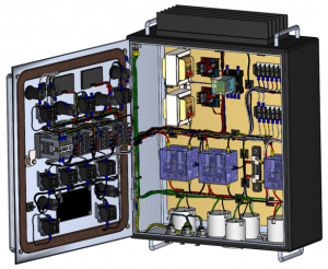
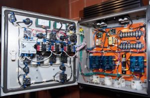
Wondering what your panel layout looks like or deciding how to lay out components before ever turning a screw can quite the imagination exercise. Fortunately for some of us, we have the SOLIDWORKS Electrical 3D add-in for our SOLIDWORKS software. Components in SOLIDWORKS Electrical Schematic are represented by many different symbols as well as SOLIDWORKS parts or assemblies. Components that have manufacturers part definition assigned to them also have a corresponding 3D part or assembly that can be inserted into our assembly to bring that imagination exercise to life.
Inserting components into those assemblies is as simple as an RMB, INSERT action. Using component intelligence will also make your insertion process easier as manual mates are continued after insertion.
To have connected wire, cable, or harness routing in the assembly requires connection points. Adding in routing CPoints will also enable further integration of your schematic foray into the 3D world. Connection points are placeholders on a component that directly tie circuit and terminal information to the component and the manufactures part definition
Prior to 2018 release of SOLIDWORKS, the SOLIDWORKS Electrical components wizard allows you to prepare a SOLIDWORKS part or assembly in order to make it compatible with the SOLIDWORKS Electrical features. The current release of the 3D now has the wizard incorporated into the routing manager.
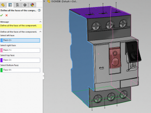
Define all faces of component
This option has you select the component’s surfaces in order to position it in its installation. Click the surfaces of the component that corresponds to the four component directions.
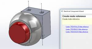
Define Mates
Another step in the component setup lets you create the insertion mates, whether the assembly is inserted on a rail, on the base or backplane of the cabinet, or on the door. Select the link you require, depending on the type of device installation.
- TREWRAIL35: Manages the mates for insertion on a rail.
- TREWBACK: Manages the mates for insertion on the back of the cabinet.
- TREWDOOR: Manages the mates for insertion on the cabinet door
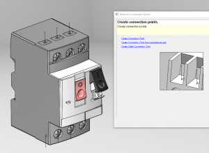
Define Connection Points
Typically the last step lets you manage the connection points used for routing. In this step, you must create a sketch which you manually place points into. These points will then be associated with the connection points of different circuits. I find a good practice to connection points is to have a reference plane the points reside on to maintain its orientation. This is especially helpful on cable points for harness and cable orientation of the fan out.
- Create Connection Point: This will create a connection point from the sketch point. Also needing to be defined are a circuit and a terminal number. This must match the information defined in the component or it will not route.
- Create Connection Point by Reference: The same information is needed, only we are pulling circuit and terminal information directly from manufacturer part from the library.
- Create Cable Connection Point: Creates a connection point on components that must receive a cable. This point is where the cable cores fan out from the jacket.
Corey Kubichka
Electrical Product Manager
Computer Aided Technology, Inc.