Advance FDM Mode Lesson 2: General Tour (Part 2 of 4)
Welcome back to the General Tour of Advance FDM Mode Part 2. After reviewing the menus, learning to add models, and learning about the selection of bodies in Advance FDM Mode: General Tour Part 1. Moving forward with our General Tour, our next steps are exploring the Print Settings menu and understanding how the Orientation menu works. Let’s get started.
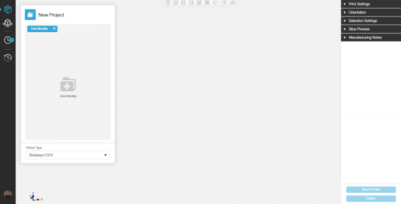
Please Launch GrabCAD and proceed to the 4th icon, Advance FDM Mode Tab. But if there are only 3 icons refer to Getting started with GrabCAD Advance FDM Mode.
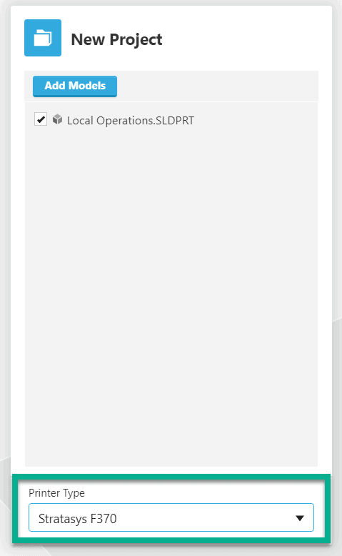
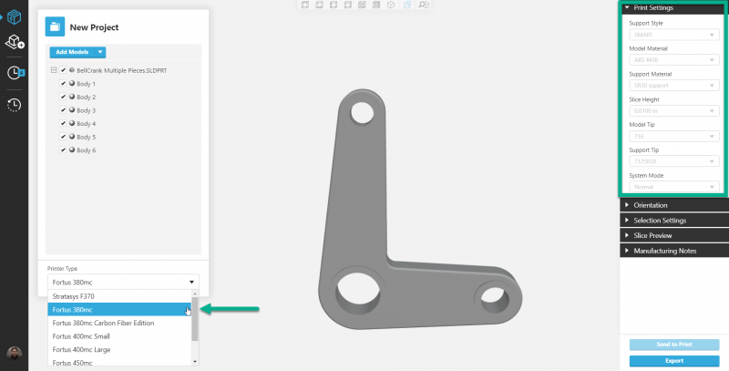
Underneath the “add Model” menu there is a “Print Type” drop-down menu with all the printers Advance FDM Mode is compatible with.
Compatible Printers:
- Stratasys F370
- Fortus Line (380 and above)
- 380mc
- 380mc Carbon Fiber Edition
- 400mc Small
- 400mc Large
- 450mc
- 900mc
- Stratasys F900
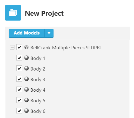
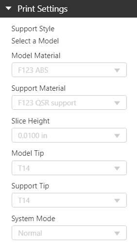
The Printer Settings Menu on the right-hand side will be grayed out if the model chosen is a multi-body part as seen below.
A way to activate the print settings menu is to merge a group of bodies and activated that group.
Notice, the grayed out Print Settings will change to different default settings if another Printer Type is selected.
Now importing a single body part and selecting the body by double-clicking, will activate the Print Settings menu.
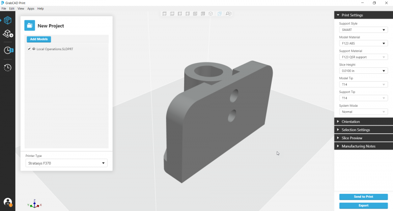
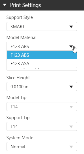
Allowing for the Support Style, Model Material and Slice Height all to be changed within the scope of the printer selected.
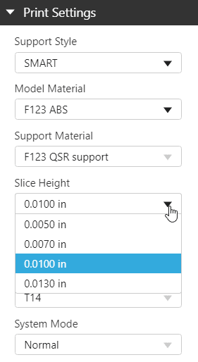
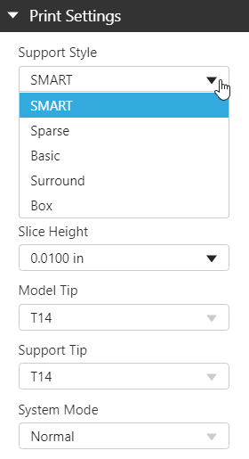
Note: Changing the slice height may require changing the tips, depending on the machine.
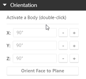
Moving onto the Orientation Menu, start by double-clicking on a part body to start.
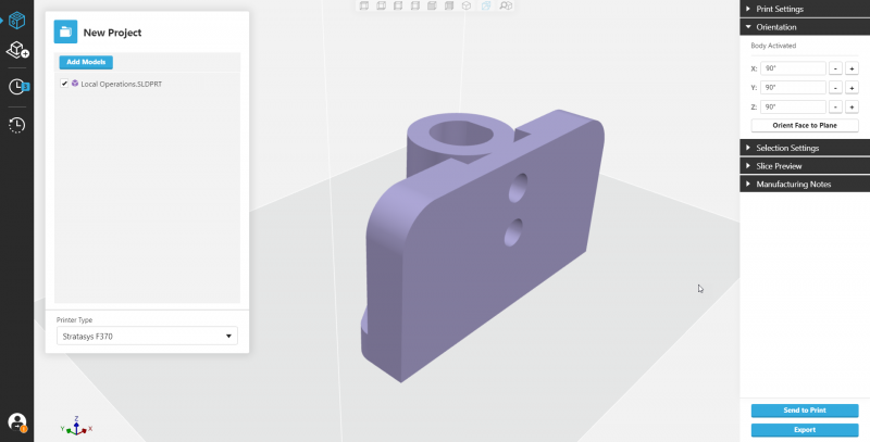
In this example, using a single body part file, we will look at how each rotation command effects the part.
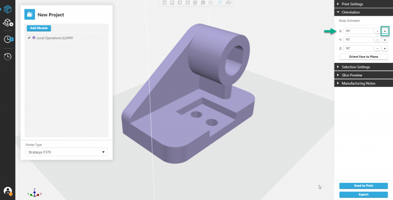
Starting with the X-axis, in the positive. (Note the bottom left for axis layout reference) We see that the part has flipped towards the bottom right-hand corner of the screen.
Starting again by resetting back to the default position.
Now flipping the part using the Y-axis in a positive direction, and we see that the part flips towards the upper right-hand corner of the screen.
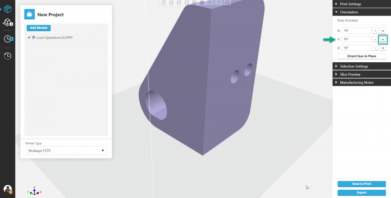
Restoring part back to default and test out Z-axis.
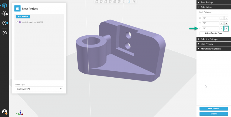
Rotating the part around the Z-axis in the positive direction. Yields a shift of the top right-hand corner of the part now pointing to the top left-hand corner. The bottom left-hand corner points to the bottom right-hand corner as well.
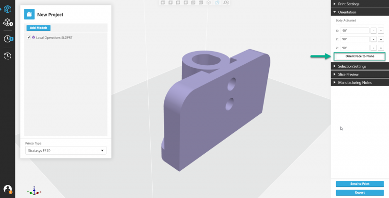
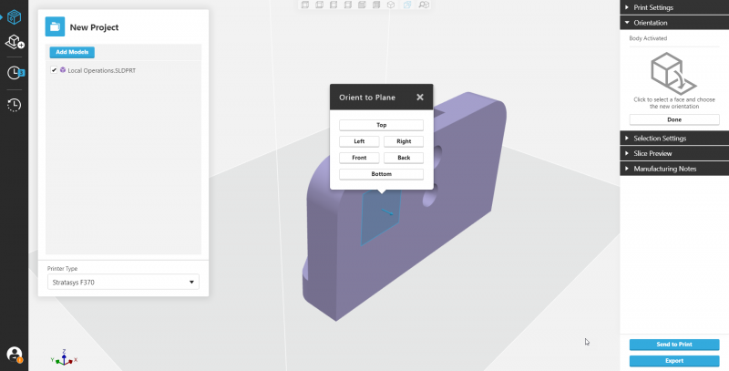
Sometimes flipping can be tough to visualize so GrabCAD has an amazing feature which allows for the user-specified part face to be aligned with the user-specified plane. Click the “orient face to plane” button at the bottom of the Orientation menu, to give it a try.
Selecting the face you want to orient the part by then…
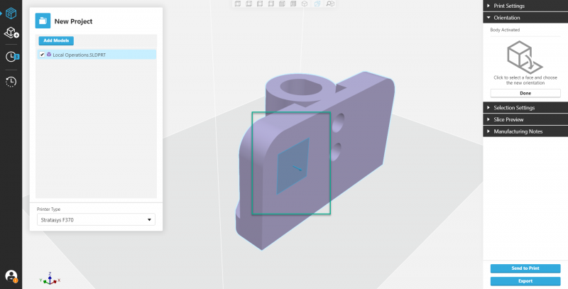
In the popup menu, select the plane to orient the face to…
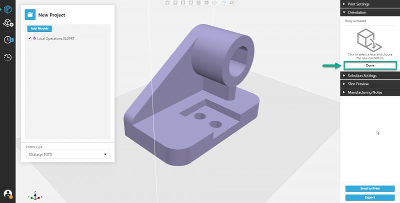
And if the results are satisfactory, click done.
We have gone over the print settings and what printers are compatible with Advance FDM Mode. In addition to that, we explored the Orientation menu and how flipping using the X, Y, Z axis buttons affect the part. Similarly, we used the align face to plan button to accomplish our task much faster and with greater ease.
This completes our tour of Part 2 and now you may proceed onto part 3.
Links to all four parts and the prequel.
Advance FDM Mode: General Tour
1 of 4: General Menus & Add Models
2 of 4: Print Settings & Orientation Menus
3 of 4: Selection Settings Menu & Face and Body tabs
4 of 4: Slice Preview Menu and Manufacturing Notes
Getting Started with GrabCAD – Advance FDM Mode
Keith Weber
Application Engineer
Computer Aided Technology, LLC