Bike Component Design with Remote Loads in SOLIDWORKS Simulation
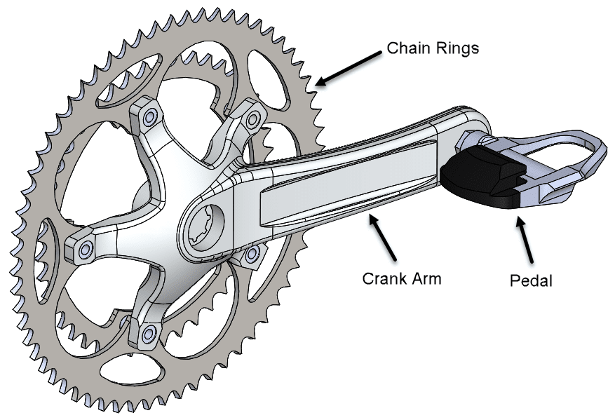
Do you perform analyses of assemblies in SOLIDWORKS Simulation that incorporate off-the-shelf components? We can usually exclude such items in the analysis, since they are typically rated for a certain load limit. I love cycling, so I’ll use the design of a bicycle drive system to demonstrate the use of Simulation’s remote load feature. The system consists of a pedal and crank arm on either side of the bike frame’s bottom bracket and one or more chain rings on the right side of the frame.
If I’m responsible for the design of the crank arms and chain rings but not the pedals, why should I include the pedals in the analysis, since the 3rd party vendor has already verified their strength? The answer is that my analysis must accurately represent the load path through the drive system, as power is transmitted to the rear wheel from the rider. The load induces a twist into the crank arm and neglecting this effect would significantly compromise the accuracy of the analysis!
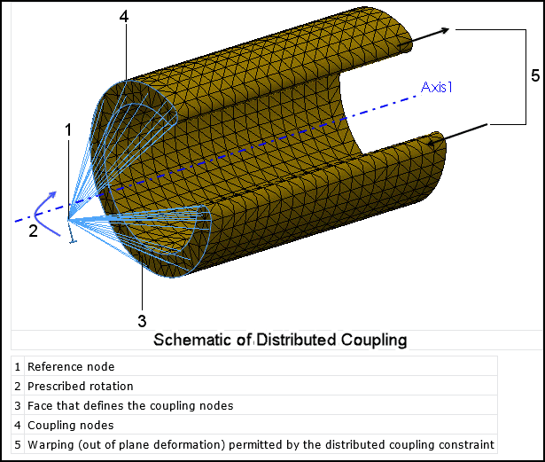
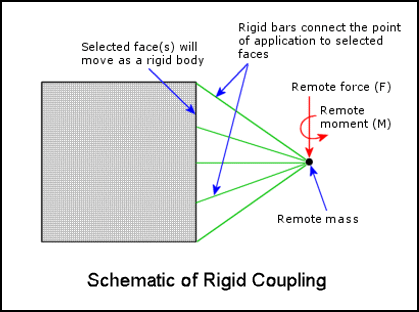
The way to account for this without including the pedal is to use the remote load boundary condition. It considers the location and magnitude of the load without the need to include the component to which the load is actually applied. The connection type (distributed or rigid), illustrated below, allows for accurate representation of how the excluded component interacts with the attachment face. Basically, this setting determines how that face will flex under load.
The load from the rider is assumed to be his/her full weight during a power stroke, approximately 160 lbs. for an average rider size, and is applied near the center of the pedal, which measures 1.83 in. from the face of the crank arm.
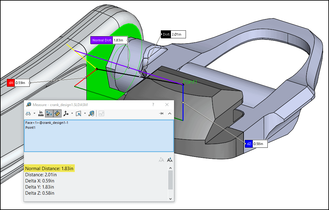
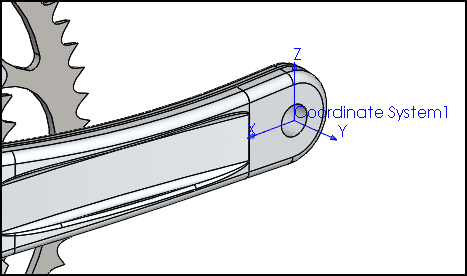
To make it easy to locate the remote load, we can add a local coordinate system to the pedal attachment face and use it in the setup as a reference (a local or global coordinate system can be used).
The Simulation study was created for the drive assembly without the pedal (all components are 6061 aluminum). An advanced fixture “On Cylindrical Faces” was applied to restrain the crank shaft like the frame’s bottom bracket does, i.e., axial and radial degrees of freedom are locked, permitting only shaft rotation.
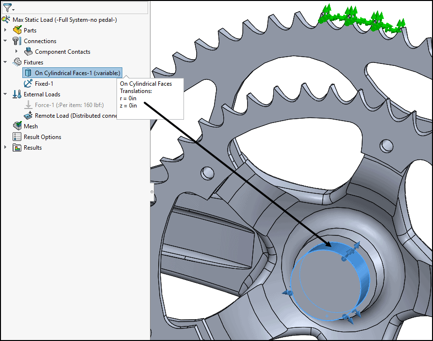
Also shown above, an additional fixture was applied to a few chain ring teeth to react the torque in the system as it would through contact with the chain.
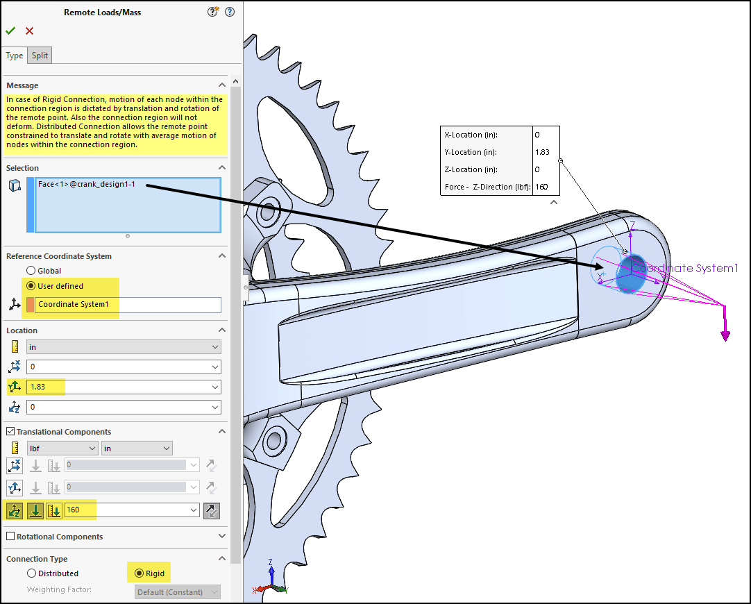
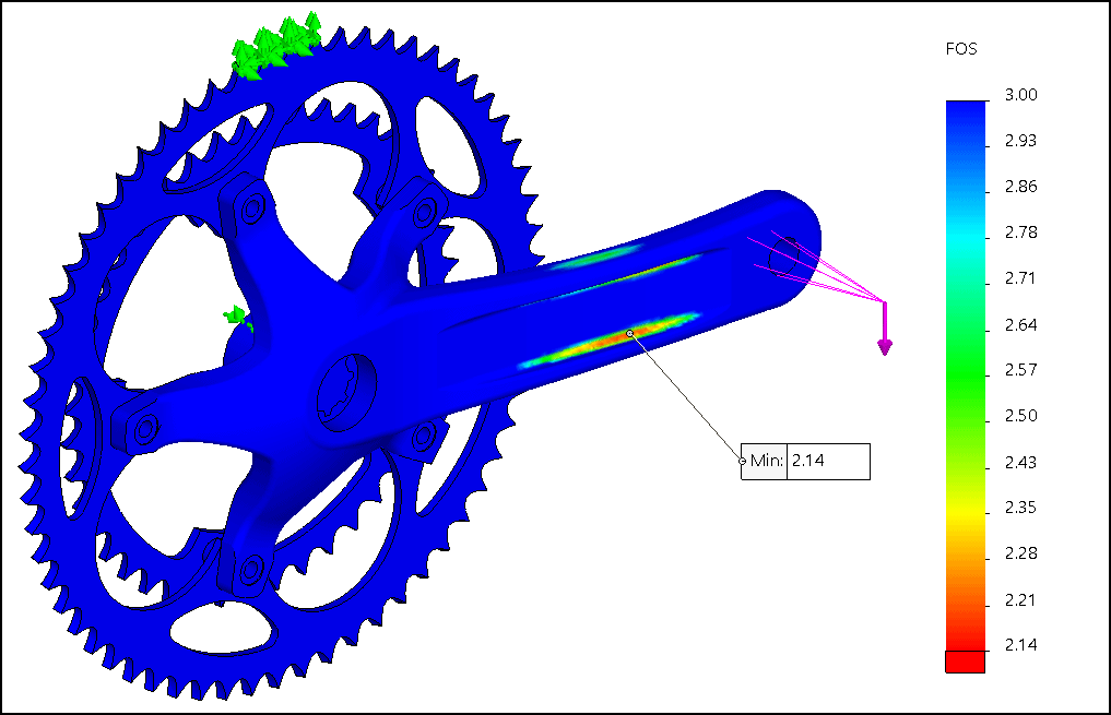
The remote load was applied as shown below. The blue Selection field is where the load will be applied. Coordinate System 1, defined previously, was set as the reference for specification of the remote load location and direction. In the Translational Components field it’s possible to specify a force or prescribed displacement. A force of 160 lbs. in the negative Z-direction was set. The Connection Type was set to “Rigid” to account for the way the pedal is threaded into the hole.
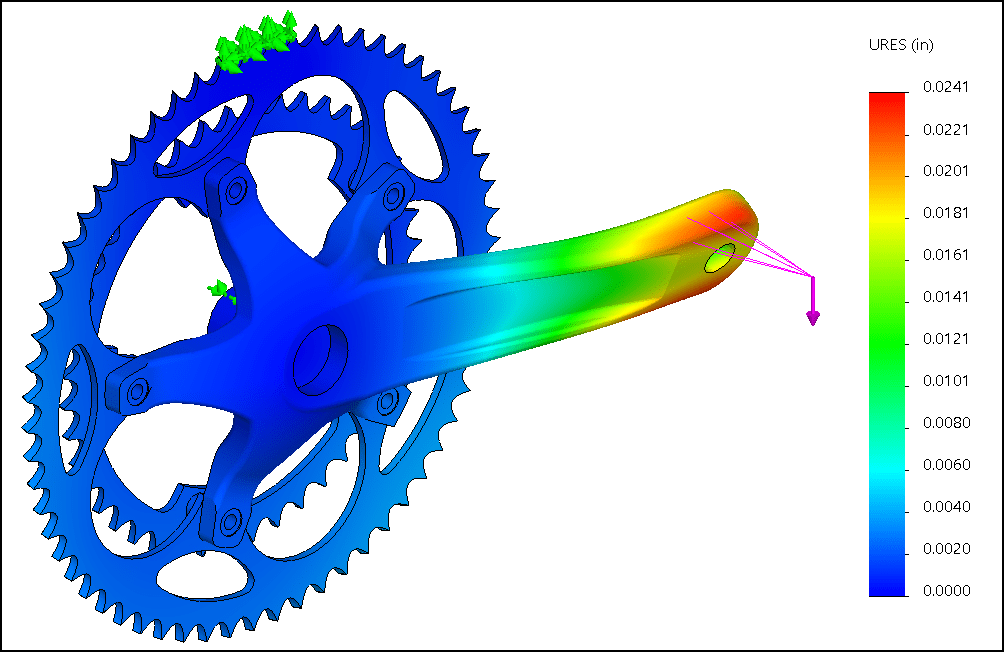
Results of the analysis on a 20X resultant deformation (URES) plot show the expected twist in the crank arm and a maximum deflection of 0.02 in. at the end of the arm. The minimum factor of safety (FOS) is just above 2.0. In cycle racing, it’s all about reducing weight so don’t forget about the great optimization capabilities we have in Simulation Professional, which could be used to reduce the weight of the crank arm while maintaining an acceptable factor of safety. Search our CATI blog page here for more information on optimization.
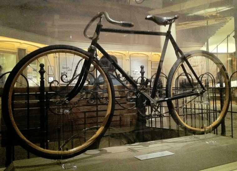
I was recently at the Smithsonian Air and Space Museum in DC and was excited to see one of the Wright Brothers’ original bicycles. Since I love cycling and flying, I was torn between it and the original 1903 Flyer in the background of this photo. I wonder what the Wrights could have done with a tool like SOLIDWORKS Simulation; I’m sure we’d be even more amazed than we already are!
Best of luck with all of your simulation efforts! Let us know how we can help. Keep on riding!
Kurt Kurtin
Technical Manager, Simulation Products
Computer Aided Technology, LLC