CAMWorks Pattern Project - Advanced 3-Axis Toolpath
CAMWorks offers several options when setting up your tool path. From different pattern type options to the granular options within each pattern, there’s a lot to digest. In this article, I will be focusing on the toolpath control options you get when using the Pattern Project strategy included with CAMWorks Milling Standard.
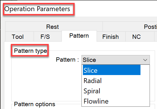
The Pattern Project operation is a 3-axis finishing operation type that removes material based on the selected pattern. Those type options are slice, flowline, radial, and spiral. Generally, these patterns are projected onto the model surfaces with the tool stepping over using a constant value for X and Y. Each pattern has unique characteristics that make them appropriate for semi-finishing and finishing selected areas or the entire model.
The Pattern Project operation could also be a multi-surface finishing cycle that removes material based on the selected pattern. Once again, each pattern has unique characteristics, making them appropriate for semi-finishing and finishing selected areas or even the entire model.
The Four Pattern Project Operation Options
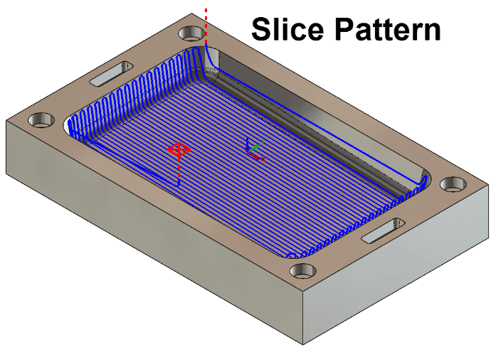
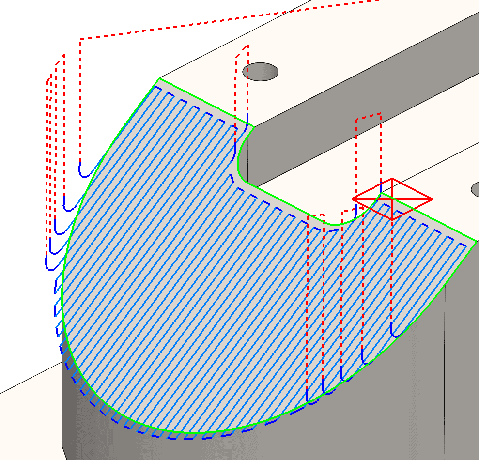
Slice is one of the pattern tool path options. With a slice pattern, you define a series of linear and parallel cutting paths across the feature of the part. Additionally, you can also control the angle of the cut with additional pattern options.
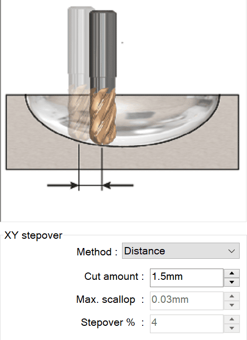
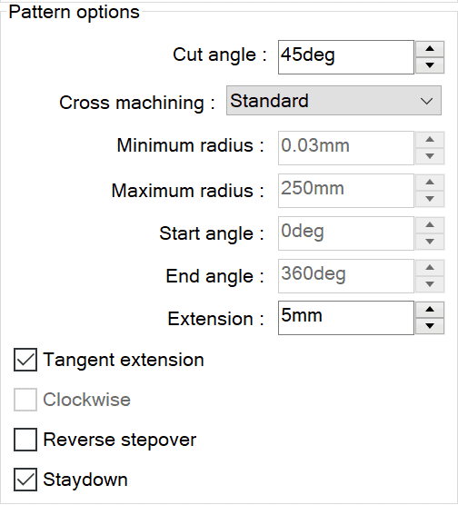
One way to use the slice pattern is for machining non-vertical areas of a part when you are trying to achieve semi-finishing and finishing of a 3-axis part feature. Here’s an example of what that could look like. In particular, I want to draw your attention to the dotted lines. These show the tool path when the mill is not in contact with the part.
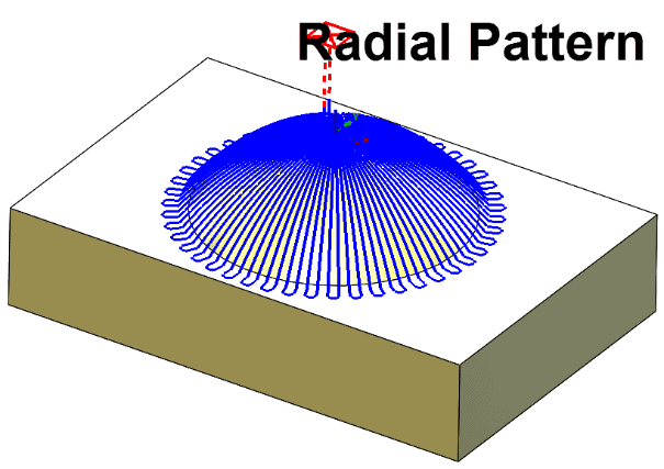
The radial pattern is your third toolpath pattern option. Commonly, we use a radial pattern for round shapes due to its unique characteristics for controlling the toolpath.
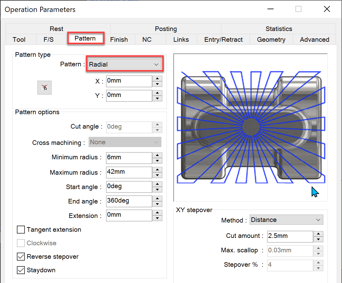
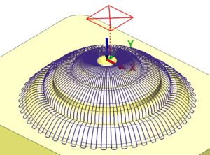
The radial pattern generates a toolpath in a radial pattern into or out from a user-defined center point and can be limited to a defined angular range.
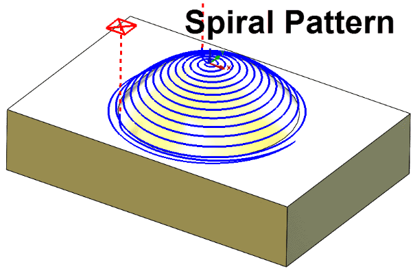
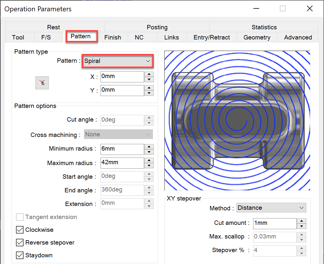
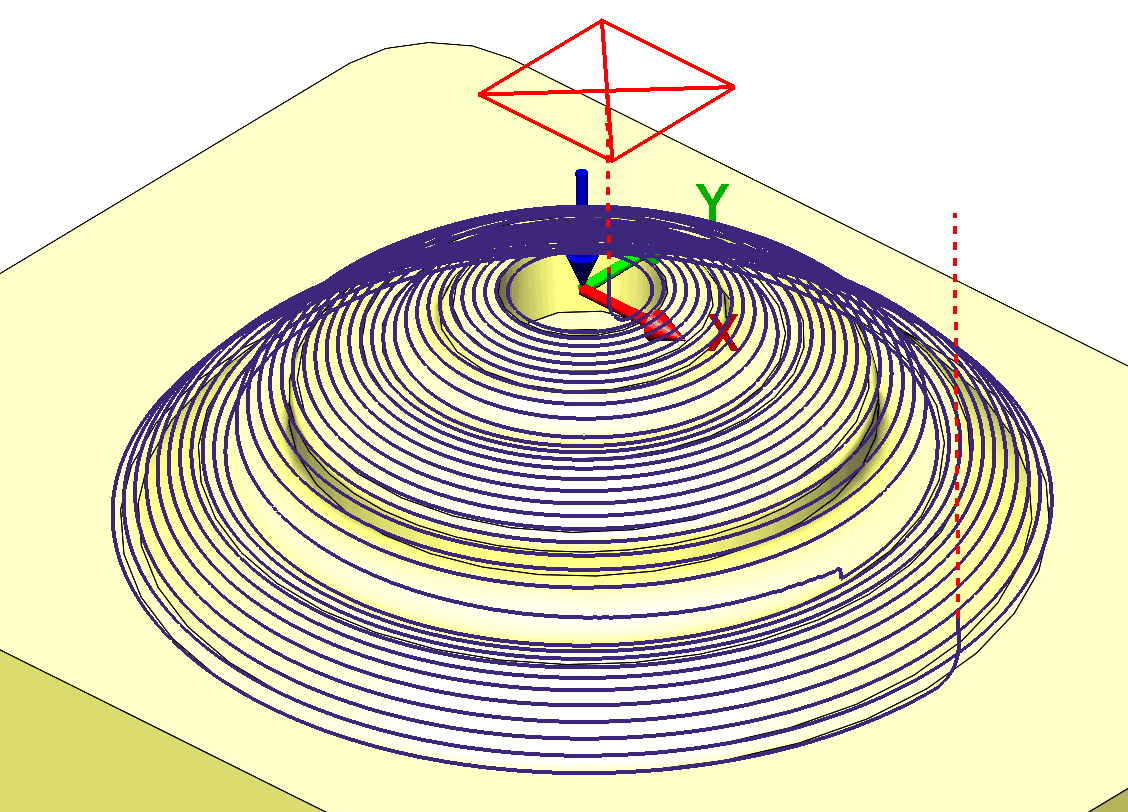
Next, we have the spiral pattern project operation. Usually, we select this option when working with round shapes, as it creates a spiral-out style tool path, based on a user-defined center point location.
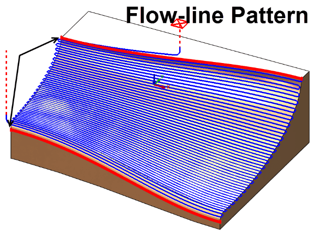
Flowline pattern is the final tool path pattern option. What flowline does is create a tool path based on two user-defined curves. The tool path is then cut either parallel or perpendicular to the curves.
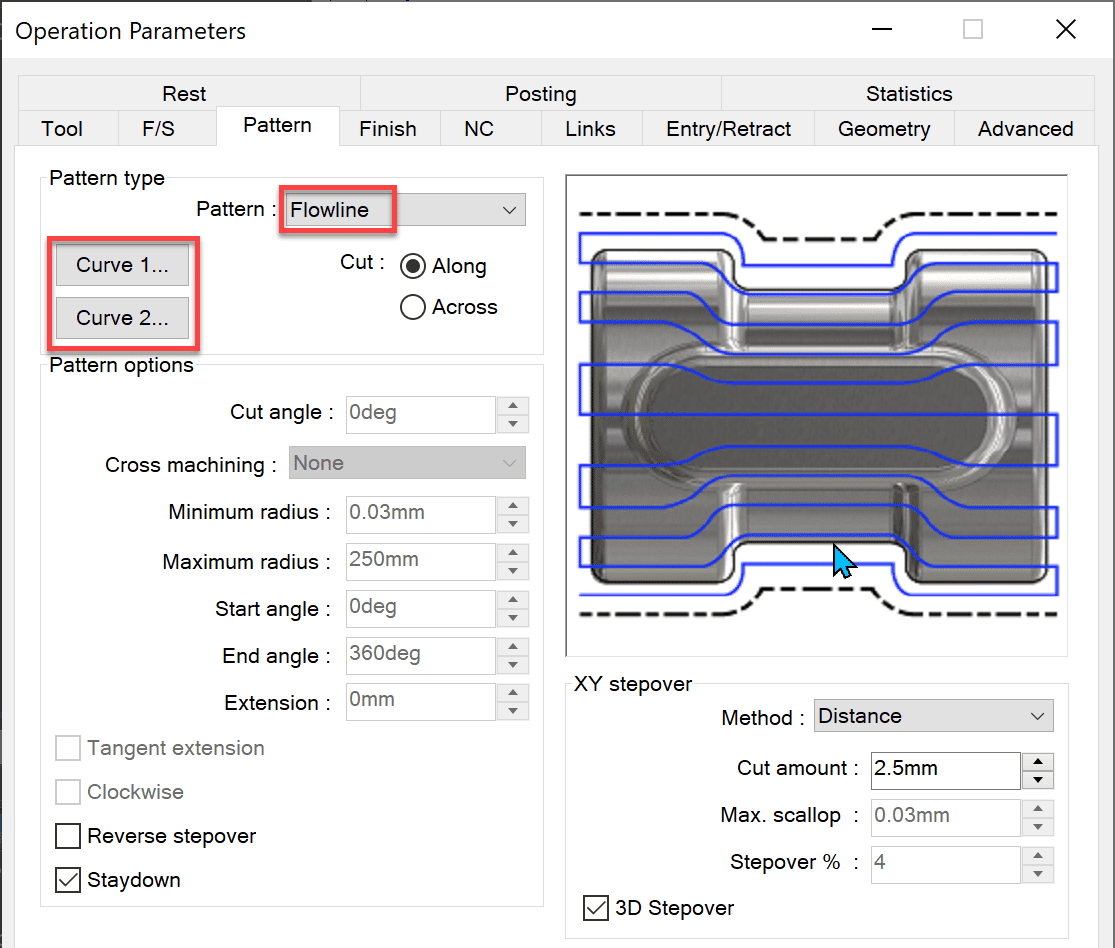
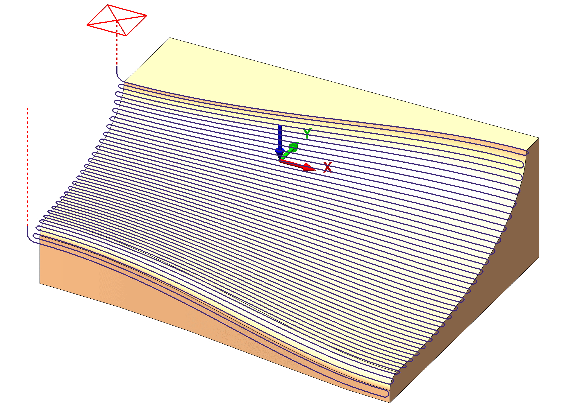
The flowline “cut along” option generates a tool path parallel to the flowlines as shown below. In this case, that means it cuts along the X-axis and Z-axis.
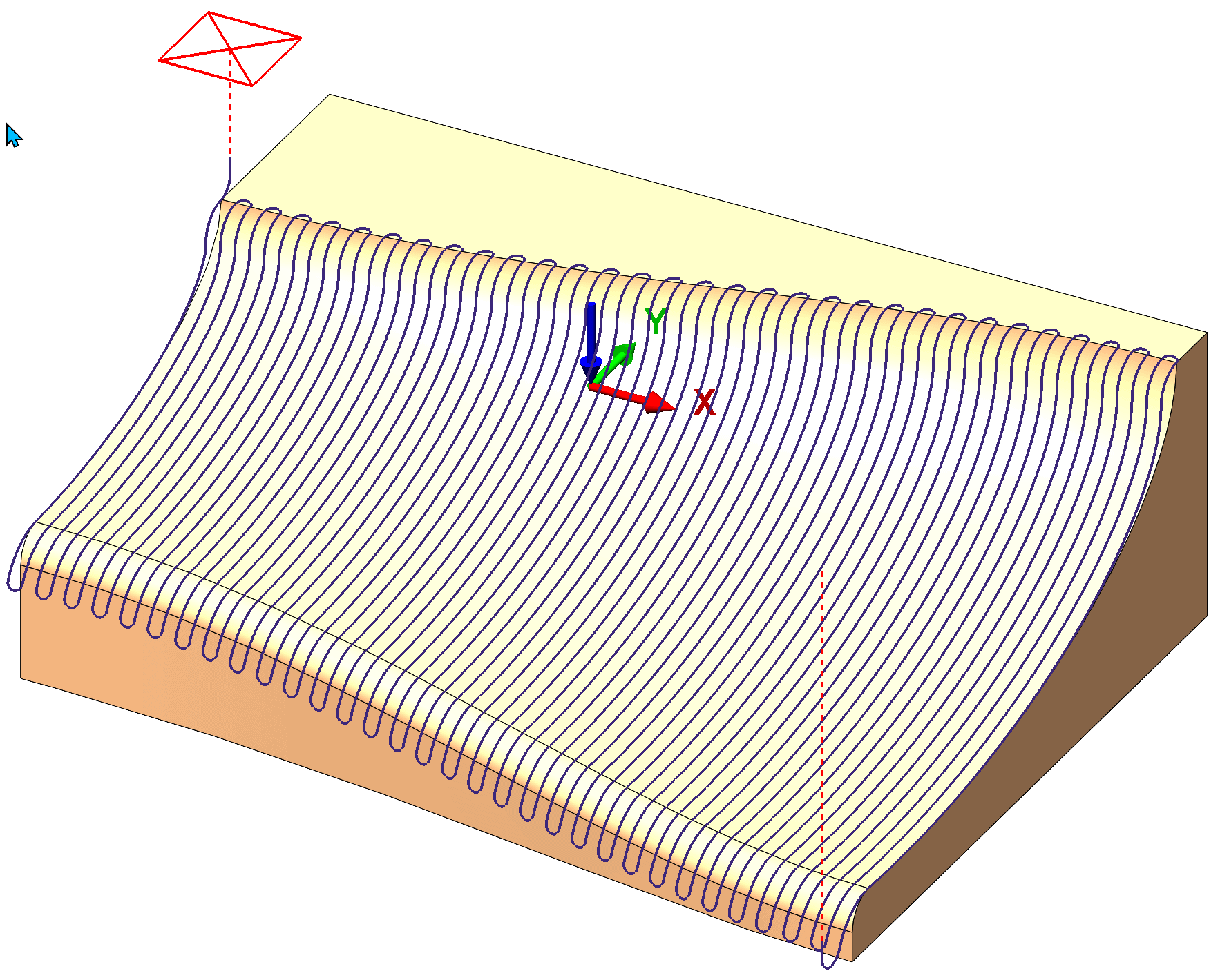
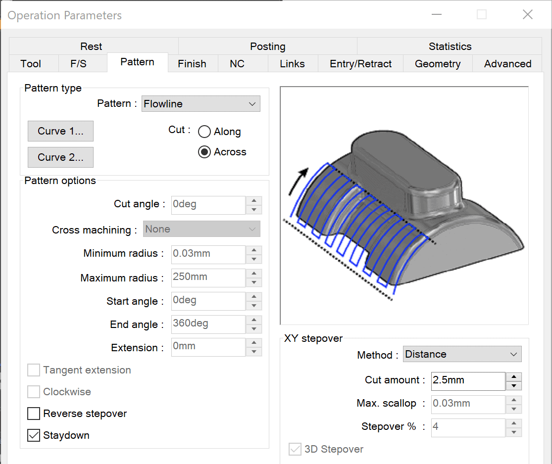
The flowline path option for cut across generates a tool path perpendicular to the flowlines as shown below. Notice, that instead of cutting along the X-axis, it now cuts across the Y-axis and Z-axis.
Additional CAMWorks Information
CATI offers a CAMWorks 3 Axis Essentials training class for more detailed content related to all of the CAMWorks advanced tool paths.
In a previous blog article, “Advanced 3 Axis Milling Finishing Toolpaths Included In CAMWorks Milling Standard”, I talked about the four additional 3-axis tool paths you get with the CAMWorks Milling Standard license bundle. Couple that with these various pattern options and you start to get a clear picture of where we can take CAMWorks Milling Standard.
Look for my next blog going deeper into other CAMWorks Advanced 3 Axis tool paths CAMWorks Milling Standard has to offer for 3 Axis tool paths.
I hope this gives you a better understanding of what CAMWorks can offer!
Don Glaske
Manager, Manufacturing/Production Solutions
Computer Aided Technology

 Blog
Blog