Cheating My Way to Par Using SOLIDWORKS Motion and a Stratasys FDM 3D Printer
I am what is known in golf as a “hacker”. If you are familiar with golf lingo, this means that I rarely play golf and I am quite bad at it. I’ll admit it! Those of you who have spent the time perfecting your strokes might relate when playing the first round of your season.
But what if I could change the negative connotations behind “hacker”, and replace it with someone who can literally hack their way through a game of golf and still compete without the embarrassing handicap? (Otherwise, start me at -10 please!)
I became inspired when I saw an advertisement of a similar device posted on a social media page. At first, I was offended at the accuracy of the learning algorithms the social media advertising uses. How could it know I am this bad at golf?
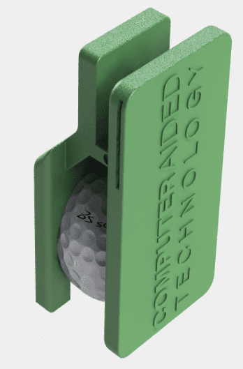
Once realizing how much time it would take me to be within +10 by the end of 18 holes, I figured it was time to hack the game myself. I built a golf ball clip that keeps the ball secured inconspicuously.
This clip is secured by a Velcro strap that is tied around the ankle and covered by the pant leg.
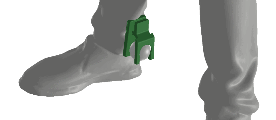
Now, whenever I shoot my golf ball and scramble to find it, with just one click of my heel like Dorothy in the Wizard of Oz, my ball magically appears from thin air – conveniently on the fairway and just within distance of the green with my 6-iron.
Shh, your fellow golfers will never suspect a thing. Well, maybe if the loser needs to buy the first round at the clubhouse.
The mechanical design was the easy part. The difficult part is determining if this design is even functional. Will that spring have enough tension to hold the ball? How can I make sure this works without having to order a dozen different varieties of springs? The answer: SOLIDWORKS Motion.
SOLIDWORKS Motion is a SOLIDWORKS Premium feature that offers time-based motion analysis. It is also available in SOLIDWORKS Simulation Standard and event-based in Simulation Professional. This function is unique from standard Simulation products because it gives the user the ability to apply motors, actuators, springs, dampers, and forces to their assemblies. This gives the assembly its unique motion. It is fantastic for analyzing mechanisms. The user can see how the part will behave after a series of driving forces are applied. In addition, critical time-based information such as motor torque required and reaction forces can be plotted and used to make design decisions on ordered parts, like the spring needed in the golf ball clip.
I will show you how I used SOLIDWORKS Motion to select a linear spring for the golf ball clip.
The first thing I did was to de-feature the dimples in the golf ball, so that it was only spherical. SOLIDWORKS Motion Analysis takes the mates assigned in the assembly and translates them to the Motion Study. Additionally, users can add motors to fix a component, instead of defining a mate. This can be helpful because Width mates, Coincident mates, and Symmetry mates are either not supported or conditionally supported (see here for more information).
After applying the mates for the starting position of the golf ball clip, I then load SOLIDWORKS Motion. A tab appears above the status bar titled “Motion Study 1”. Selecting Motion Analysis (#1 from figure 1) from the drop-down menu gives the user access to the general functions of SOLIDWORKS Motion. Some of these features will be otherwise suppressed if not properly selected.
Here is the general layout of the SOLIDWORKS Motion Dashboard (2020):
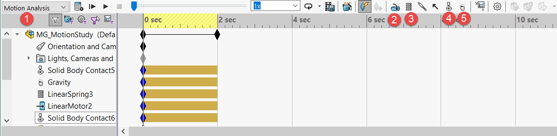
Figure 1: Select “Motion Analysis” (1) to utilize all tools such as motors (2), springs (3), contacts (4), and gravity (5).
Applying gravity (#5 in figure 1), I’m simply looking at the reference triad in the corner and telling SOLIDWORKS which way is “down”.
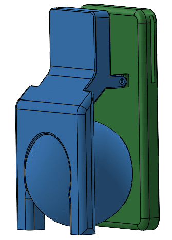
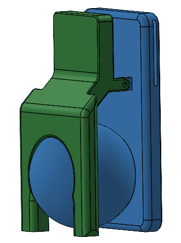
Then, I need to add contact sets (#4 in figure 1). This is how I detail which parts interact with others. I am going to apply two contact sets here (shown in blue) in the image below:
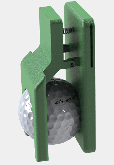
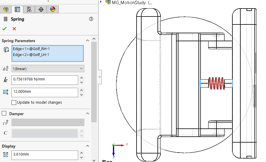
Next, I add the spring we are interested in (#3 in figure 1). It is as easy as adding a stiffness and free length of the spring. Dampers can be optionally added, as well as how the spring is displayed (actual length, outside diameter, wire diameter). It is important to note that the display is only temporary, and SOLIDWORKS Motion adds the mathematical equivalent constraints for the spring. I used a standard spring from McMaster-Carr to fill out these values and to customize how the display looks. For the ball to be supported, it would have to be pre-loaded. I needed a spring that was longer than the space between the clip.
Lastly, I needed to simulate someone pressing the clip lever. I used a motor here, though a user could just as easily use a force. Since I did not know the force required precisely, a motor is more appropriate. I can then look at the motor forces to see if the ball would be easily unclipped or not.
After hitting “Calculate”, I am now able to see the motion and plot the reaction forces from the spring.
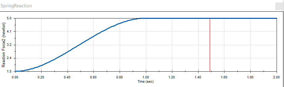
Spring reaction force:
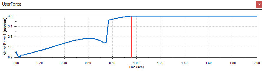
User input force:
Note: the “blip” on the user force plot is not unusual, this is the ball leaving the clip at this moment. The maximum force exerted by the motor is 3.8N, which is relatively low and would be easy for the user to release.
The results are in: I need the spring to be able to withstand a minimum of a 5N force. I also need to make sure that the max load length is less than the open (end) position of the clip. The spring I hand-picked from McMaster-Carr has a maximum load length of 4.6 mm, so the end position of the clip needs to be greater than 4.6 mm.
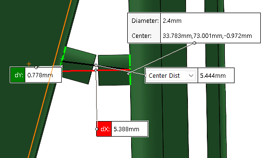
The max compressed length is around 5.4mm, which is perfect for application.
Now that my design has been validated, it is off to the 3D printer. I am using a Stratasys F370 for this. The best part about 3D printing is that it allows for rapid design changes. For instance, it wasn’t until I printed the component that I realized the tabs that connected the hardware were too small. The size makes this susceptible to breaking. I beefed that up before continuing the print. Voila! We have a physical product that functions exactly as intended, without the need for expensive re-works.

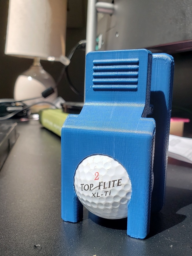
The finished product worked great! The spring fit perfectly, and was snug enough to hold the golf ball while walking. After one or two suspiciously positioned balls, my golf buddies were both amazed and amused when I revealed the secret to my success!
Though this blog post was a break from the norm and was meant for entertainment purposes, this should also give you an idea of how useful SOLIDWORKS Motion is. SOLIDWORKS Motion can eliminate the hard math and guess work of sizing motors, springs, and forces. It can also be used for hand calculation validation. SOLIDWORKS Motion is so much more than just animating assemblies.
I hope you, too, can harness and conquer the power of SOLIDWORKS Motion. Whether it’s sizing actuators both big and small, or if it’s just to improve your golf game, Motion bridges the gap between design and concept validation.
If you are interested in learning more about Motion, you can contact your CATI Business Development Manager for a demo. Additionally, check our blog for more help with SOLIDWORKS motion.
Setting up Motion Simulation Contacts
Using Motion to Understand Joint Forces
As always, Happy Designing!
Jordan Kleinschmidt
Application Engineer, CSWE, CSWP-S
Computer Aided Technology, Inc.