Coordinate Systems in SOLIDWORKS: How to Make Them and Why You Might Need ‘em
Creating a new coordinate system inside of SOLIDWORKS is a simple enough task to complete. You just need a point! But sometimes getting that point is the hardest part of the process. In certain industries like automotive, a specific coordinate system may be absolutely required for reference, along with exportation.
How to Make ’em
To create a new coordinate system, I’ll first need to ensure I have a point in space to reference. This can be many different items:
- Sketch end point
- Geometry vertex
- Origin
- A reference point
But the point you select is driving the new location of the coordinate system. 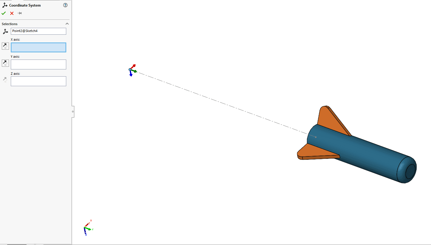
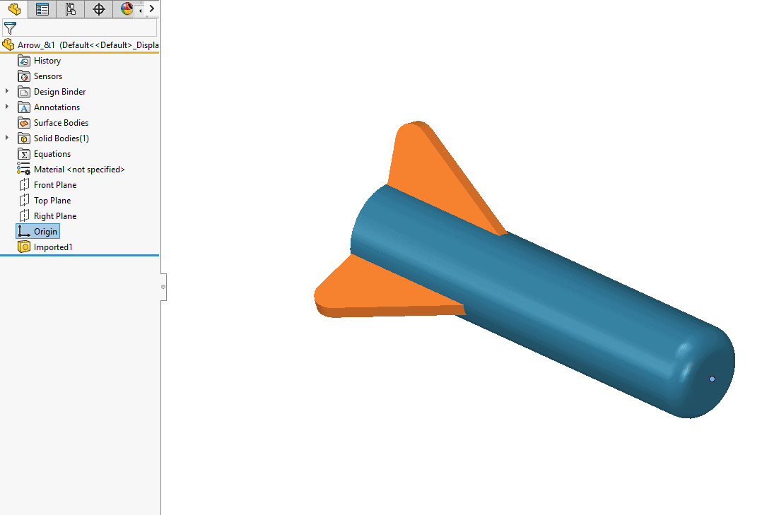
Creating new points using the reference geometry Point is easy enough as well and a great way to define locations. For example, if I wanted a point on the center front face of this dart, I could choose Point, then select Center of Face, and select the face on the front to define that new point location.
After defining a point in space, I can then select the Coodinate System under reference geometry to define my new one.
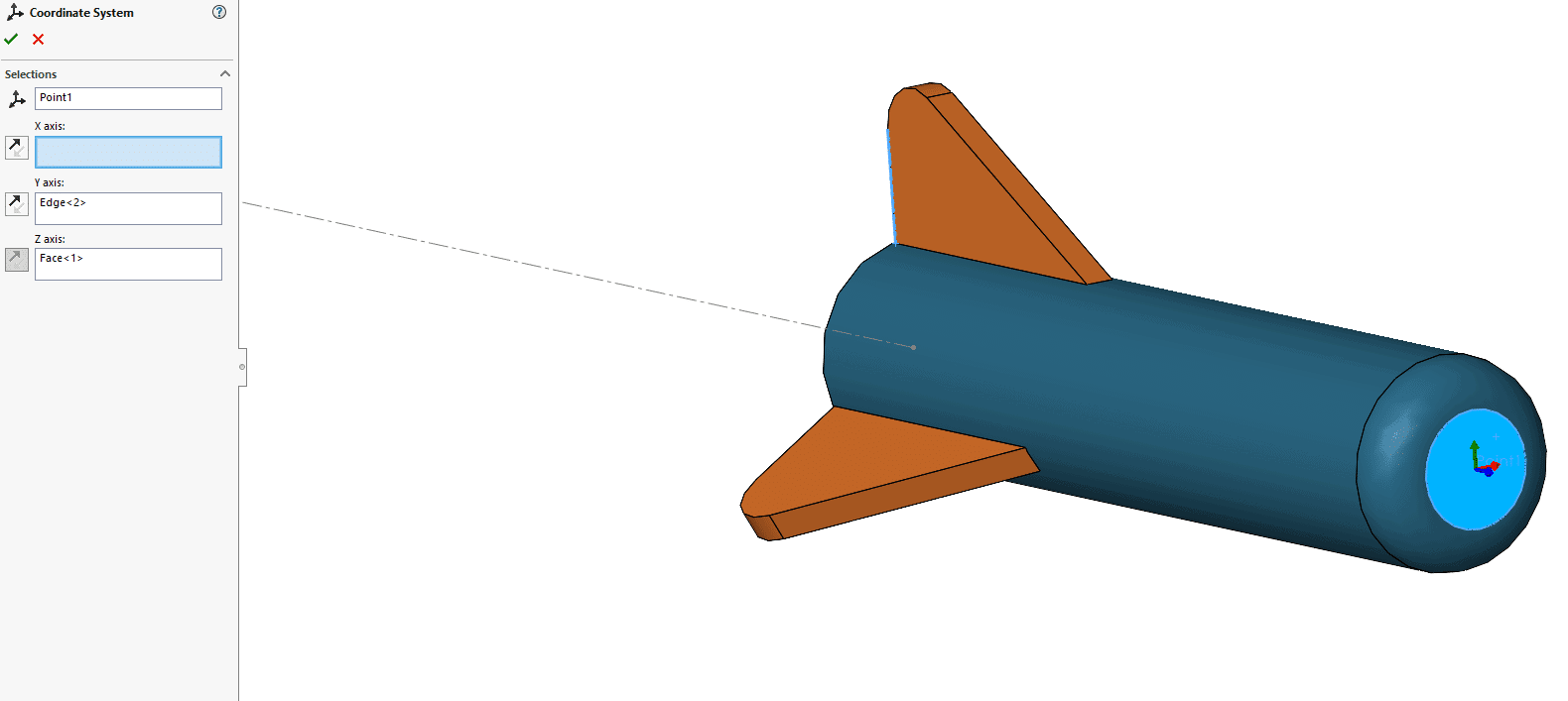
In my property manager, I have four boxes I can define. The first is my Point, setting the new origin of my coordinate system. The next three are determining the orientation of the X, Y, or Z Axis. Selecting from a numerous amount of choices:
- Vertex, points, midpoints
- Linear edge or sketch lines
- Non linear edge or sketch entity
- Planar Faces
How it can be Used
Once the system is created we can do a few different things with it.
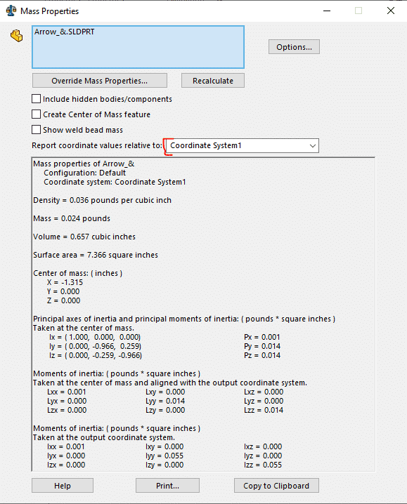
First, in my mass properties, I can report values relative to the new coordinate system.
Second, I can use it when exporting the file in a neutral format. Whether I need it for 3D printing origin location or for setting the part in an exact position in space.
I choose the file format, select Options on the bottom of the window and in the options window Select Output Coordinate System to change from Default to your selected Coordinate system.
Finally, I can use it to define a new orientation about my Measure tool. Helping to guide the XYZ of the measure tool and giving me good information in my distancing analysis.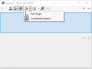
For any questions, please feel free to reach out to support or myself personally at David.Janicki@CATI.com
David Janicki
Application Engineer
Computer Aided Technology, Inc.