SOLIDWORKS and solidThinking: Designing a Filtration Unit
Recently, as I was drinking a cup of tea, I appreciated having hot and clean water to drink. I thought about the process of obtaining that water. Specifically, about the filtration process. I wondered, what if I could simulate the filtration process within SOLIDWORKS? I quickly realized that I could do more than simulate the filtration process. I could simulate the casting of individual parts as well as the injection molding of specific parts of the apparatus.
With that understanding, I set forth to utilize SOLIDWORKS Flow Simulation, SOLIDWORKS Plastics, and solidThinking’s Click2Cast software to optimize the design. In this blog, I will lay out the steps to analyze a filtration unit with three different simulation and analysis solutions.
SOLIDWORKS Flow Simulation
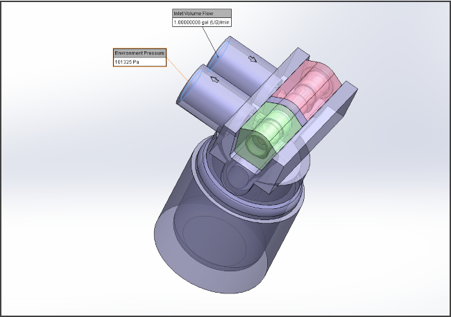
The first step to beginning any type of computer aided engineering analysis (CAE), is to model the part within a computer aided modeler; in this case the filtration apparatus. The filtration apparatus shown below was created within SOLIDWORKS 3D CAD. The basic understanding is that the water will enter the system via the arrow shown on the diagram, circulate in the small chamber below, and then move its way outward through the system via the outward arrow indicated in the figure below.

One of the great advantages of working with SOLIDWORKS Flow Simulation, is that Flow Simulation is completely embedded into the CAD interface and therefore geometrical changes can be updated on the fly. It should also be noted that SOLIDWORKS is also able to directly import a variety of CAD formats into SOLIDWORKS, which can then be subsequently used in Flow Simulation. With the filtration model drawn and built into the model, I can begin a new SOLIDWORKS Flow Simulation Analysis.
SOLIDWORKS flow simulation is an extremely powerful tool and can be utilized for a variety of problems. In this particular scenario, I am interested in optimizing the design in regards to pressure drop and outlet flow velocity. I want to see how this particular design impacts the flow path as it moves its way through the system. I set forth in making sure the appropriate boundary conditions are applied, in this case, I know the inlet water flow and the environment pressure on the filtration system. I apply the boundary conditions as indicated in picture below and then mesh and run the model.
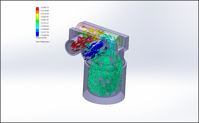
After successfully running this model, I am able to see how the flow is circulating as indicated in the figure below. I am also able to obtain the overall outward flow and pressure drop. The design meets the flow objectives, and I can move into the next phase of analysis, SOLIDWORKS Plastics.
SOLIDWORKS Plastics
Design for manufacture can be a tricky part of the design process but with the use of SOLIDWORKS Plastics, the user can simulate the entire injection molding process. The advantage of this is that the designer can determine if they should either change the geometry or the material that the part will be manufactured from. For this particular analysis, I want to utilize SOLIDWORKS Plastics to analyze a retaining ring.
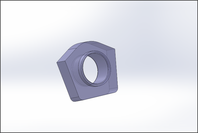
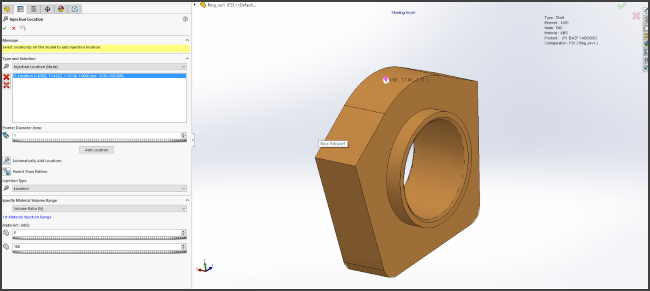
In the filtration device, there is a retaining ring between the two metal slots. The ring is a custom shape and it is not something that can be purchased from a supplier, as seen in the figure below. Therefore, the part must be made by a plastics manufacturer, and with the use of SOLIDWORKS Plastics, we can determine how our desired retaining ring will respond to plastic manufacturing.
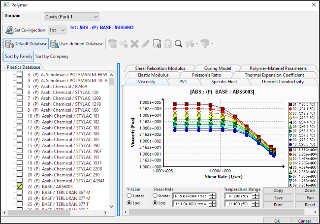
With SOLIDWORKS Plastics we can select the polymer, the fill settings, and the injection location along with all other appropriate settings to simulate the manufacturing process for this ring. For this part, we selected an ABS plastic for the retaining ring as shown below. We also specified the fill settings and injection locations on the top of the retaining ring.
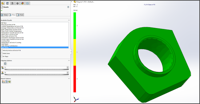
Upon setting up all of the appropriate injection and plastics settings, we can then run the analysis to see the overall effect of trying to manufacture this part. SOLIDWORKS Plastics determined that based on the polymer and fill settings, that this retaining ring will be able to be adequately manufactured, as indicated in the picture below showing the ease of fill.
SolidThinking Click2Cast
As we have worked through this filtration device we have determined that the overall design would satisfy our flow conditions. We also determined that the retaining ring would be able to be successfully manufactured via SOLIDWORKS Plastics.
We now want to take a look at how some portions of the filtration device could be manufactured on the metal side, specifically casting. Traditionally, casting softwares have been extremely expensive to use and been fairly complicated to utilize. However, Fisher Unitech is offering a new solution that will do a casting analysis: solidThinking’s Click2Cast.
This new software is much more cost effective than other casting software and is extremely easy to use. We are going to utilize Click2Cast to take the inner piston and run a casting analysis on that part. The purpose of this is to determine if this part can be easily cast, or if we need to make modifications to the material or overall geometry of the piston.
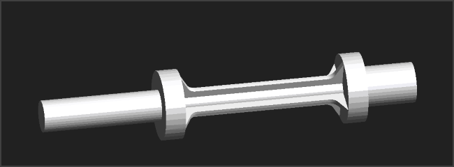
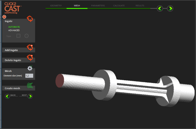
The first step to start a casting analysis in Click2Cast is to save the piston SOLIDWORKS file as an STL file and to then open up that file as a new project within Click2Cast. Much like SOLIDWORKS plastics, the process of setting up a casting analysis requires picking a material. The next step is to pick the gate or location where the material is going to flow through. For this particular piston, I selected aluminum with a gate location on the end of one of the pistons as indicated in the figure below.
Upon selecting the gate and the material, I selected the fill time and then ran the casting analysis. Through the casting analysis, I can determine how difficult this part will be to cast for the material and geometry of the part. I can also look at solidification of the part and the specific porosity of the part as shown in the figure below.

What the figure is pointing out is there are some small porous areas but the part is able to be cast successfully. If the porosity is of concern, than the fill time can be adjusted or the gates can be modified. If you are still having issues with porosity, than the material or geometry should be modified. However, with this piston we are satisfied with the casting analysis, and through Click2Cast we were able to determine that the part is relatively easy to cast.
Through utilizing SOLIDWORKS Flow Simulation, SOLIDWORKS Plastics, and solidThinking’s Click2Cast, I was able to properly model the filtration unit that is used on a daily basis.