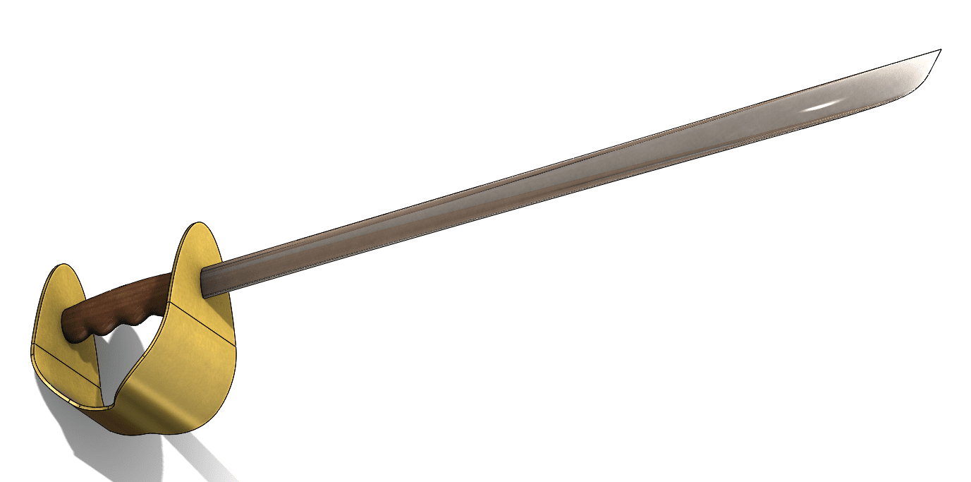
Design Your Halloween Costume Props in SOLIDWORKS
Well, it looks like Halloween is coming, so what better time to get in the spirit of things and start making some props for the little minions (aka kids) to use with their costume? My man-cub has been exploring the idea of being a pirate, so in pure engineering fashion I started to wonder how I could incorporate some Pirate sword designs in SOLIDWORKS.
This sword design is going to incorporate multibody surfaces that we’ll eventually convert to solids. In this blog, I’ll walk you through some of the steps and explain the features used to create this sword.
The Pommel
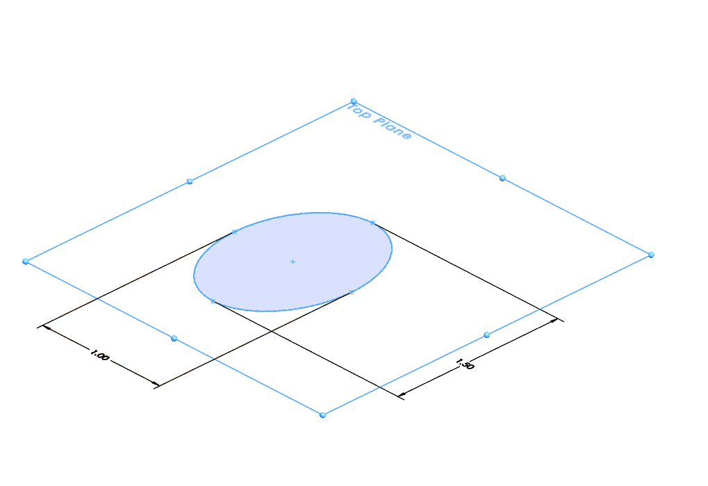
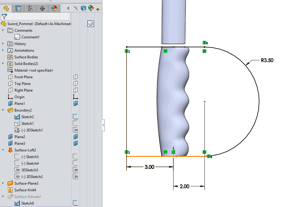
Naturally we’ll start (as all things do) with a sketch. However, this sketch will create geometry that serve two purposes. First of all, it’ll create reference geometry for us to make other features, but It’ll also serve as geometry to cap the ends of our swords pommel grip. I’ll start this sketch on the TOP PLANE.
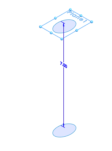
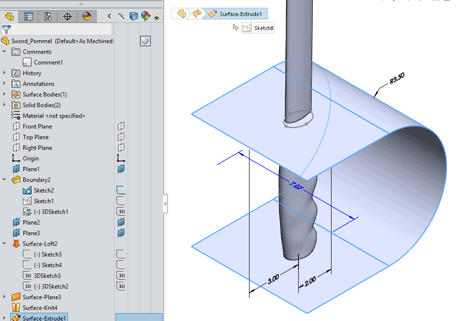
Now that I’ve made one sketch, I’ll set the height of the handle and pommel with a plane to start another sketch of the same ellipse, offset a distance of 7” from the first sketch. This will set me up to place a loft between the two sketches for my Handle.
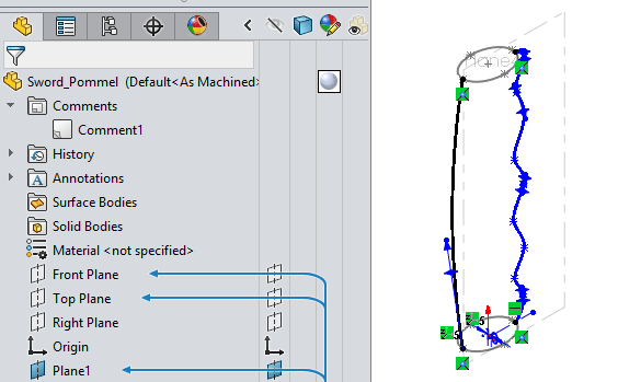
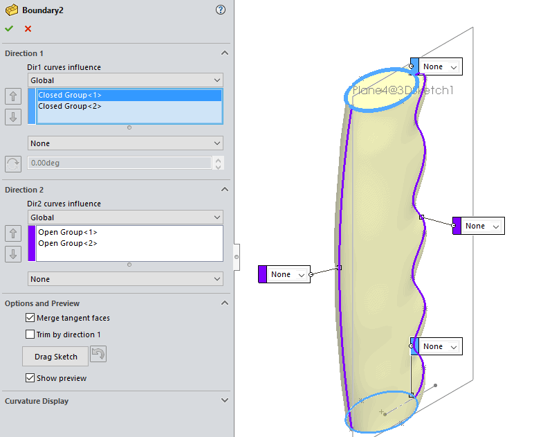
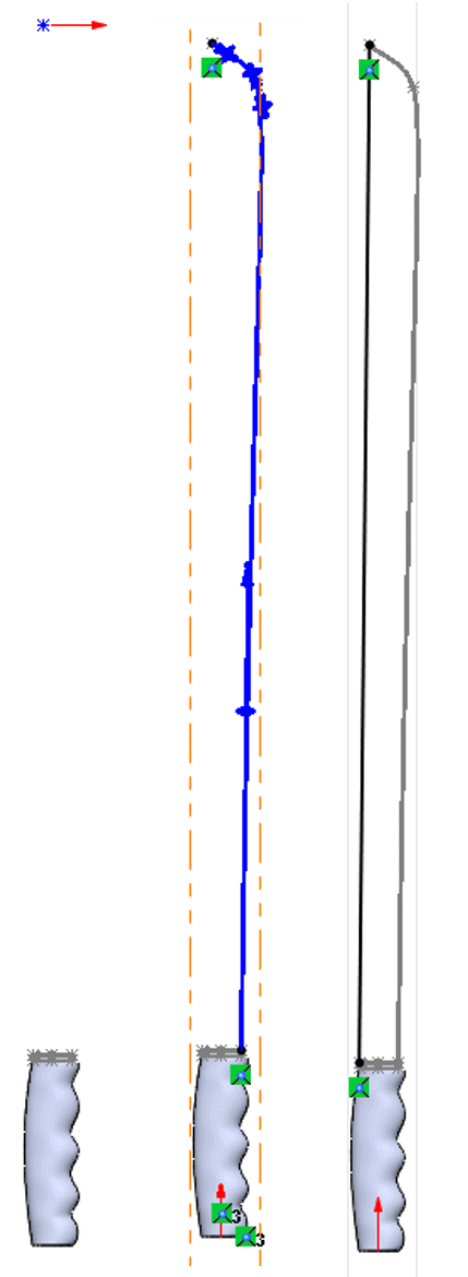
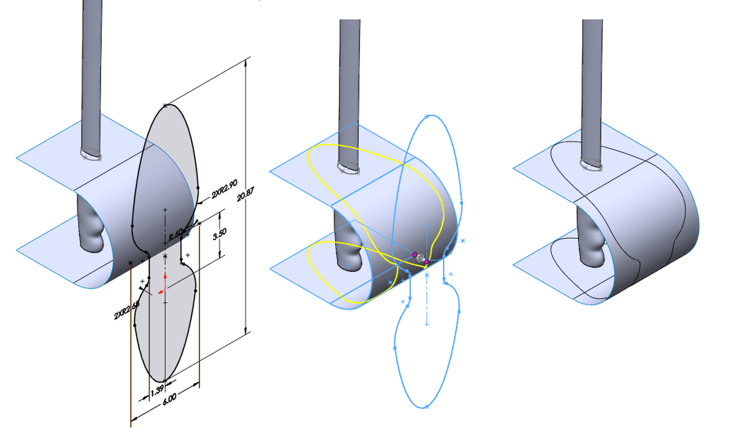
Now we’re getting into the “meat” of things as, the next feature will require a set of sketches to be executed properly. I’ll start a 3D sketch on a 3D sketch plane, coincident with the right plane, and create the handle profile. This sketch will involve two splines. One will shape the back side of the sword grip, while the other will shape the finger grooves of the grip. This will require some work with the spline handles.
Once I relate both entities to the upper and lower and lower sketches I’ve created, I can then start my Boundary loft feature. In the property manager for my boundary loft, I’ll select the edges of the two planar surfaces I’ve already created, and then use the two splines from the 3D Sketch that we just sketched. I’ll check the box to “Merge tangent faces” and keep my curve influences set to “Next Edge”. The preview shows me that the loft is good to go.
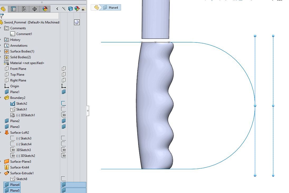
Once my loft is complete, I can now start setting up my planes for my next set of sketchs. These next sketchs will set up another loft for our blade. While I’ve avoided doing it in this blog, I usually name my features, so that I can keep them organized. I’ll start my first plane on the top of my grip, and the second will be offset 39” from the top of the grip.

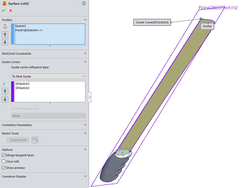
On the top plane I’ll start a new sketch with a point place vertical of the origin. This point will literally be the point of my blade. I then use convert entities to copy the top edges of the grip onto my bottom plane to use as reference geometry for my loft. I’ll then create two 3D sketches with relations to the sketches on PLANE 2 and PLANE 3 to shape the actual blade.
With a profile now set, I can set my loft up using the profile I created on the top of the grip, and the point at the top of the blade profile. The two 3D sketches I made provide the guide curves needed to shape the blade.
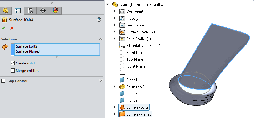
I’ll do another plane and sketch on the bottom of the blade loft to create a “cap” with a planar surface. Now I have 2 surface bodies, and 1 solid body. Since this blade purely consist of surfaces, I’ll need to knit the surfacebodies together to unify them. While I’m in the property manager I’ll create a solid while I knit the surfaces. This will leave me with two solid bodies in my feature tree.
Now we can start on the hand guard. This hand guard is going to cover most of the grip, so I’ll sketch using a tangent arc from the line tool to create the profile I need. I’ll start my sketch from the from the right plane, so I can use a mid-plane surface extrusion for my guard.
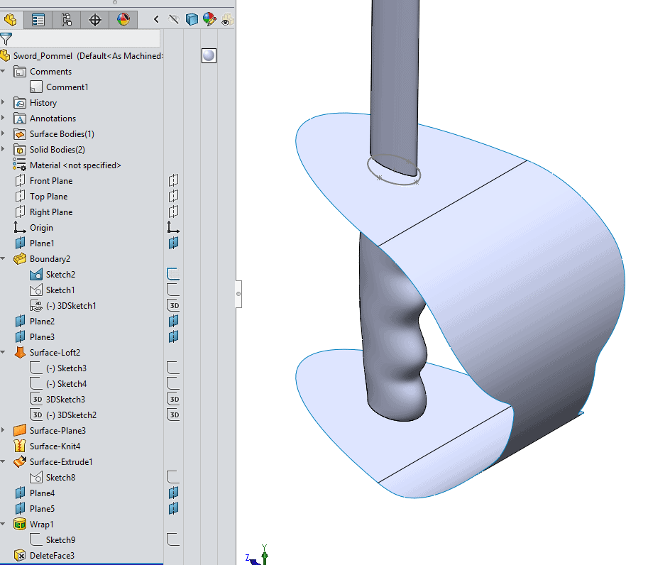
While we could keep this curved shape for our hand guard, I’d like to make it just a little bit more ornate, so I’m goind to use the surface of the guard as a projection screen to place another profile. To do that, I’ll need to make a reference plane that is tangent to the guard, and other plane offset from that tangent plane. The last plane will give me a sketching surface with clearance from the guard to draw my profile.
I’ll now start a sketch on the further plane and draw a profile that I would like to wrap around the hand guard. This is a simple profile using a ellipse and one slot that have been trimmed to make this shape. One the sketch is complete, I’ll use the wrap feature to apply to sketch to the guard face.
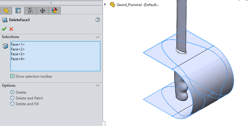
Once this is complete I can use “Delete Faces” to trim away the unwanted surfaces using the “Delete” option.
Once the guard is trimmed, I can now thickin the surface using the “Thicken” feature, and add some appreances. Now you have a perfect weapon for virtual swashbuckeling!!!