Using SOLIDWORKS 2017 Sheet Metal Enhancements
Sheet metal parts are common across a wide range of industries from special machines, housings, and other critical product components. When your work involves creating sheet metal parts, you need the most flexible design approach possible. This includes flattening functionality. SOLIDWORKS 3D CAD software gives you the ability to do all of this and now the new SOLIDWORKS 2017 release gives you even more critical new functions.
Four main features in SOLIDWORKS 2017 that have been enhanced:
- Three bend corner relief
- Normal Cut has improved flattened results
- Punch Table support for mirrored and derived parts
- Define individual options per sheet metal body in a multibody part
I’m excited to show you the new 2017 functionality. Improved manufacturability, less confusion from the manufacturing floor, and improvements in the interface will result in a better return on investment with SOLIDWORKS. Now let’s take a look at some examples I’ve put together for you.
Three bend corner relief
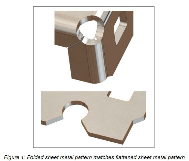
Ever had an issue where the manufacturing floor is confused as to why your flat pattern looks different from the folded model? I’ve been there and always had to explain it as “that’s how the software works.” It could be faked in older versionsbut was time-consuming. In 2017, three bend corner reliefs now work. You can make your folded sheet metal pattern match your flattened sheet metal pattern as in Figure 1 below.
Normal Cut has improved flattened results
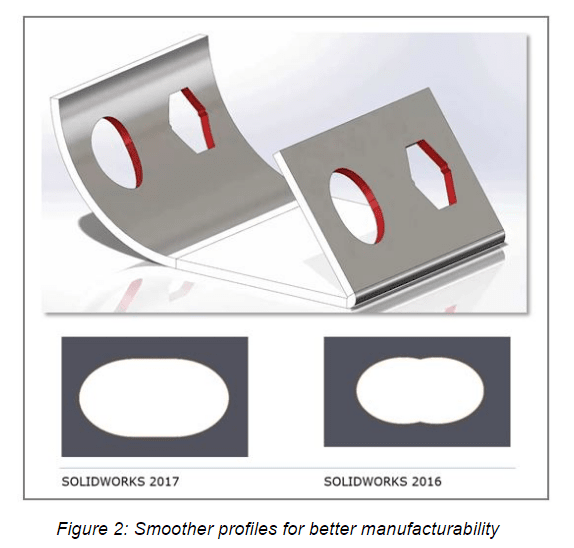
As punched hole geometry is created in curved faces, the results of the cut in a flattened state could produce odd geometry that would sometimes need to be touched up in SOLIDWORKS 2016. That geometry is nice and clean in 2017. In sheet metal parts made before 2017, edit the feature and make sure the Normal Cut and Optimized Geometry have been checked. This will create smoother profiles for better manufacturability as in Figure 2 below.
Punch Table support for mirrored and derived parts
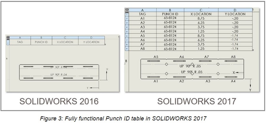
In past versions of SOLIDWORKS, if sheet metal bodies with form tools used on them were mirrored (to create a whole component) there would be an improper number of tools referenced in the punch table. Basically, it would ignore the amount of tools from the mirrored body side. The same thing would happen if the component was used as a derived part. Now in 2017, the punch tables will reference all form tools even if mirrored. Derived parts just need the sheet metal information box checked to ensure all form tool data will come over to the new part.
In Figure 3 below, the part on the left was a mirrored body from an assembly. None of the punch’s show up as a callout. In 2017, we see a fully functional Punch ID table.
Define individual options per sheet metal body in a multibody part
Prior to SOLIDWORKS 2017, the initial sheet metal body component controlled all the default settings of any other body created. We can now control the default behavior for each individual body. These may be things like relief, bend and default parameters. You can save this option in the template file to override default parameters or keep the behavior from 2016 and earlier. It’s your choice.
Conclusion
These great new options add up to increased sheet metal performance in SOLIDWORKS 2017 that will enable you to do more than ever before.