Don’t Get in Trouble, Go With a Bundle - SOLIDWORKS Electrical: Wire Harnessing
SOLIDWORKS Electrical: Wire Harnessing
Within SOLIDWORKS Electrical, you can create and design an electrical wire harness with tons of information linked to the harness. How is this done? Well keep on reading!
Using the schematic tools, you can define the terminal connection points within the harness. This will allow the harness to be built in the 3D environment of Solidworks. Designing a wire harness will be a process starting with the development of a schematic, applying the components to 3D space, wiring the components, and finally developing a drawing for the harness.
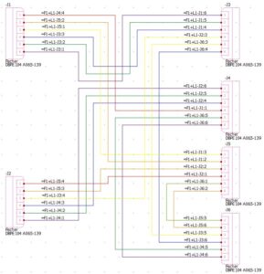 Developing the Schematic
Once the schematic and cable details have been completed and the components have been associated, everything can be selected and added into the harness. This will allow the software to understand how to generate a model of your harness.
Designing in 3D Space
Using SOLIDWORKS Electrical 3D, you can now take your design and implement it. The harness takes the lengths of the wiring line based on distance between components and routing guidelines. Adding the components from SOLIDWORKS Electrical is simple with a component tree to track all of your electrical components. Any additional information such as routing guidelines can be easily added as well.

Once all the components are in, you’re ready to wire! Simply click, “Route Harnesses”, and watch your work near completion. The software will then create your harness. From here, you can modify and refine how the harness looks.

Creating a Harness Drawing
Once the harness is completed, you can create a harnessing drawing. Using the Routing: Electrical tools, use the feature, “Flatten Route”. This will take the harness, along with the connectors, and create a flattened harness drawing. You will have the option to either create an annotation view of the harness, which is a compact representation, or you may choose a manufacturing drawing which creates a ‘nailboard’ type drawing.

In the figure below, you can see a version of the annotation harness drawing. You may edit the route by right-clicking the harness and selecting, “Edit route”. Here you may choose different changes such as making the connectors vertical. Once you have the harness looking neat and organized to your standards, you can select, “Flatten route”, an additional time and this will output the harness into a drawing with BOM, wire table, cut-list table.

Because this harness is connected to SOLIDWORKS Schematic, the bill of materials can also be created on the schematic side to include parts and pin locations. Creating a harness can be daunting but with the right tools, it can be made simply!
Post By: Brian Do, Electrical Product Specialist, MCAD Technologies