Dual Dimensions in a SOLIDWORKS Weldment Cut List
Have you ever needed to represent both English Standard and Metric measurements in a cut list in SOLIDWORKS? Do you have multiple vendors, with multiple different unit preferences? Everywhere you look, you see forums suggesting “this can’t be done”, or that SOLIDWORKS has yet to make this an option. In fact, you can find (and vote on) an enhancement request for SOLIDWORKS to do exactly this (SPR 585270, SPR 722498). The purpose of this blog is to show you otherwise. This can be done, and all it takes is a little ingenuity.
First, I will lay the foundation and start with how a cut list works, then I will explain the difference between a cut list and a Bill of Materials (BOM) and, lastly, I will show how this can be utilized quickly and easily.
The default SOLIDWORKS cut list is to be used where sheet metal components and structural members can be defined as components of a part or an assembly from stock. It is comprised of an “item number” in which bodies within a part are assigned, a “description” which is saved to the weldment profile template as a custom property, a “quantity” of stock components required, the length of each weldment item, and the necessary sheet metal bounding box size, if applicable. Cut lists are extremely useful in providing lengths and size requirements for this purpose.
So, why not just have a radio button where I can toggle “ON” dual dimensions in the weldment cut list?
The answer isn’t quite so simple.
Although I could easily represent lengths using dual dimensions, the problem is when I try to also interpret the description. The description, which is a custom property, cannot be mathematically calculated because it is a text string. This leaves the dual dimensions half-complete and rendered useless. To find a way around this, let’s first take a closer look at how a cut list table and BOM table are similar, but different.
The main feature that differentiates a BOM from a cut list is that a BOM will (by default) focus on part-level components, whereas a cut list focuses on bodies within a part. Therefore, if a user defines a multi-body sheet metal or weldment part within a BOM, critical information is missed if not using indented BOMs. The user will need to create an indented BOM to allow for cut list components to show.
Another key differentiator are the property types that can be assigned to new columns in each table. The table below details selections that can be made by using either a BOM table or a weldment cut list.
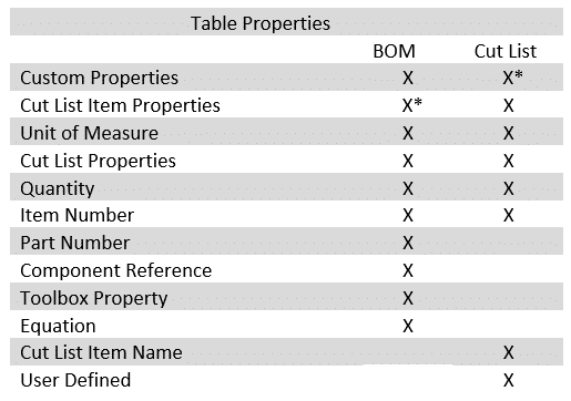
* value represents limited options
Apart from the cut list item name, a BOM can do nearly everything a cut list can do, and more. This brings me to the grand reveal – Dual dimensions require a BOM, not a weldment cut list, to function as desired.
This is because of one specific table property being available in BOM: the “Equation” property. Using the equation property will allow me to be able to represent all dimensions in dual format, and this is how:
First, add a BOM. Change the BOM type to Indented, Flat Numbering to most closely represent a weldment cut list. Delete “Part Number” column if desired.
Add a new column. This column will be used to represent the length of the weldment components. Under Column Type, select “Cut List Properties” and select “LENGTH”. This will define the length of the components based on the default unit setting of the current drawing.
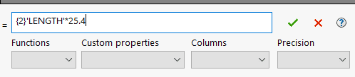
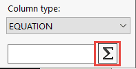 Add a second column. This is where the benefit of using a BOM to represent the cut list comes in. I am going to use this second column to represent the secondary unit. For the table property type, select “Equations” and click the sigma symbol.
In this dialog box, I can use previously defined columns as a multiplier to get the correct calculation.
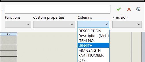
I will select “LENGTH”, and since my default units are “Inches”, I will multiply that column by 25.4 to get the metric result. In curly brackets, {}, I include the precision I want the evaluation to calculate to. I chose to have a precision of 2 decimal points. Not adding a value here will prevent rounding and hence will lead to precise results but can also create trailing decimal values.
With the column fully defined, I will title this column “MM-LENGTH”.
Now, all that remains is the “Description” in metric format. Remember that this is a text string value tied to a custom property in the weldment cut list, so you may have a strong intuition for where I can add this secondary value…
The answer: Store the metric dimensions as a secondary description within the weldment template file.
First, determine where the weldment profiles are stored under Tools> System Options> File Locations> Weldment Profiles. Copy the folder path if necessary, save the drawing, then close SOLIDWORKS. Re-open the application by right-clicking the application and selecting “Run as Administrator”. This allows you to make changes to the default read-only files that are protected by SOLIDWORKS. (Which reminds me, do not forget to back up the folder before making changes to SOLIDWORKS default templates!)
Once SOLIDWORKS is open, go to the file path and open the profile you want to add metric units to. Go to File> File Properties and activate the “Configuration Specific” dialog. Click “Edit List” to add a new custom property to define your secondary unit measurement. I defined mine as “Description (Metric)”.
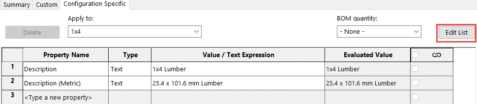
Now I need to add the value to the text box. I need to do the manual math to convert the units. In which case, 1×4 lumber turns into 25.4 x 101.6 mm lumber. Please note that these are not the true dimensions of a 1×4 piece of lumber stock, actual dimensions are 1.5”x3.5” (19 x 89 mm) after post-processing. The description value is not meant to provide an accurate measurement, but to define the stock type.
Go through all remaining configurations by using the “Apply to:” drop-down menu to add the custom text.
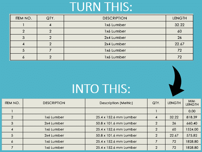
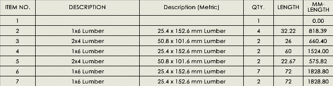
Lastly, open the drawing with the incomplete BOM template stored. Add a column to include the new custom property that was defined in the weldment profile. The BOM table now looks like this:
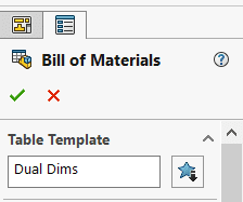
Once formatted properly, do not forget to save this BOM template by right clicking the symbol at the top left of the table. Store this on a network location or in your file vault for use in a collaborative environment.
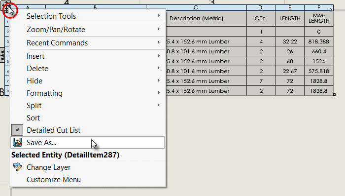
Remember, you can re-load a BOM template by adding a new BOM, then clicking the Table Template import option, as depicted in the image below.
Now that you understand how custom properties work and how you can use a BOM to represent dual dimensions, you should be able to apply similar techniques to detail any dual dimensions for sheet metal components as well, though this will not be elaborated on for sake of brevity.
Dual dimensions, although not directly available with weldment cut lists, can be created with just a little ingenuity. The article highlights how BOMs and weldment cut lists work, as well as a step-by-step instruction for how to implement this in your place of work. Please contact your SOLIDWORKS sales rep if you are interested in learning more ways that we can support you.
I hope this helps, good luck, and happy designing!
Jordan Kleinschmidt, CSWE
Application Engineer
Computer Aided Technology, Inc.