Everything in Its Right Place…The Mystery of Weldment Profile File Structure
Let’s have a little talk about structure. Every day, we deal with structure through hierarchy, process, organization, and much more. We deal with structure every minute and hour of our waking lives. As confining or depressing as that might sound, there are benefits to structure.
In some environments, structure provides familiarity and ease, two things we tend to embrace in the digital world of file management. SOLIDWORKS offers a wide gamut of control and flexibility across the many software functions available to users.
The Weldments function allows users to design structures using welded structural members, while keeping them organized in a cut list table. The structural members themselves are driven by profiles created as 2D sketches. Users can choose from one of the many profiles installed by default, or they can save 2D Sketches as library features to use as profiles. This allows users to create a near endless array of profiles to drive structural members to their liking.
How does this work? Well, it’s a combination of file organization, location, and yes, you guessed it…..Structure.
Weldment profiles are essentially two-dimensional sketches created with strategically place entities and relations to represent the cross-section of structural members to be joined together. These relations allow the user locate the orientation of the structural member to relation to the geometry being created.

Profiles can be created in nearly any shape as long as they have the proper entities to allow accurate placement on the supplementary sketch use to drive lengths and corners of a weldment structure.
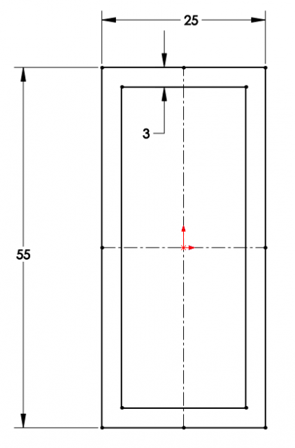
Let’s take a look at creating a basic profile. The first thing I want to do is create a new sketch on a standard plane. Once in the sketch space, I’ll draw a basic center rectangle with construction lines “from midpoints”. Construction lines from the midpoints will allow me to have control point on all sides of my profile. Once the rectangle is complete, I’ll use “Offset Entities” to create a smaller rectangle inside my first one with an offset of 3mm. This offset will be my material thickness.
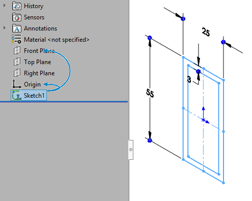
Once my offset is complete, I’ll exit my sketch and select the sketch in the feature tree. Once my sketch is selected, I’ll select “save as” from the save drop menu (under the disk icon) and change the file type to library feature part (.sldlfp).
Now this, is where most folks get lost…
SOLIDWORKS likes to have weldment profiles saved in a specific structure depending on the format of the library feature. Here’s two things to remember with weldment profiles:
1. Simple standard profiles require a subfolder for
a.Type
b. Size
2. Configured standard profiles only need a subfolder for
a. Type
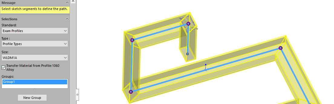
Simply stated, if we were to look at a file tree for a standard weldment profile, a “simple”(non-configured) profile needs individual subfolders to map the profile type, and size. This structure mirrors the selections in the “Structural Member” property manager shown. This leaves a folder address like below:

Configured profiles on the other hand, allow the user to consolidate profile dimensions permitting multiple configurations of that profile to be stored in one library feature. Configured profiles still populate the property manager the same way, but the profile does not need a subfolder allowing a folder address like this:

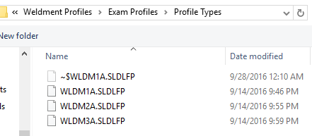
As such, when I save this particular profile, I’ll need to place it in a folder holding the profile standard, type, and size. In this case my folder structure is:
Weldment Profiles:
• Exam Profiles
• Profile Types
Once the profile has been saved in the right location, a small “L” will become present on the profile sketch in the feature tree. This mark indicates that it has successfully been saved as a library feature part.
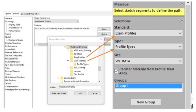
We now need to tell SOLIDWORKS to look in the root directory for these profiles to be mapped to the software using “File Locations”, found in “System Options”. After choosing “Weldment Profiles” from the “Show folders for:” pulldown, I’ll navigate to the root directory for my weldment profiles. This will allow SOLIDWORKS to place all of the subfolders needed for my profile exactly in the right place.
Now that my profile is correctly mapped to my software, I can walk through the familiar steps of applying it to a sketch via the structural member feature.
Well that about wraps it up on weldment profile folder structure. As always, if you have any questions feel free to contact our engineering team for the best solutions.