Explaining Catalyst EX build properties
CatalystEX allows you to take full control of how to build your part. The Properties window is accessed from the General Tab.
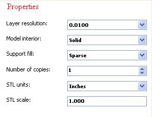
Layer resolution – height of each layer of material extruded to produce a part. Available resolutions are based on printer type.
.007 inch (.178 mm) Elite Only
.010 inch (.254 mm) Elite, 1200, and uPrint
.013 inch (.330 mm) 1200 Only
Resolution will effect build time and surface finish – A shorter height creates a smoother finish, but will take longer to build.
Model interior – establishes type of fill used for interior, solid areas of the part.
Solid – used when a stronger, more durable part is desirable. Build times will be longer and more material will be used.
Sparse – high density (Elite, 1200es, uPrint 3D Printers only) – this is the default model interior style and it is highly recommended. Build times will be shorter, less material will be used, and the possibility of part curl for geometries with large mass will be greatly reduced.

Sparse –low density– the interior will be “honeycombed/hatched”. This style allows for the shortest build times and lowest material use.
Support fill – support material is used to brace the model material during the build process. It is removed when the part is complete. Support fill options will affect the support strength and build time of the print.
Basic – may be used for most parts. It uses a consistent spacing between the support raster tool paths.
Sparse – minimizes the amount of support material. Sparse uses a much larger spacing between raster tool paths than basic supports.
Minimal – is used for small parts that have small features in need of supports. It is designed to make support removal easier on these small parts. Do NOT use minimal supports on large parts or parts with tall columns of support.
Break-away – similar to sparse supports without a closed tool path-perimeter curve. They are easier to remove than other support styles but build slower than sparse supports (not available for all printers).
Surround – the entire model is surrounded by support material. Typically used for tall, thin (narrow) models (e.g., pencil).
Number of copies – select the number of copies you want to Print or Add to Pack. The number of possible copies will be limited by the size of the modeling platform. Multiple copies sent to Print will first be saved as a Pack_.cmb file. If using the Add to Pack button, each click will send the same number of copies to a Pack – if space allows. From the Pack Tab you can view the arrangement of the part(s) on the Modeling Platform.
STL units – select ‘inches’ or ‘millimeters’ units of measure for your STL file. STL files do not specify units of measure. You need to specify the units as either inches or millimeters.
Example: An STL file of a cube designed with a dimension of 100 X 100 X 100, opening with a unit of measure set to inches, will not fit within the build envelope. By changing the units of measure to ‘millimeters’, the part will be resized – and fit within the envelope.
STL scale – before you process a part for printing, you can change the size of the part within the build envelope. Every part has a pre-defined size within the STL file. After you have opened the file you can change the size of the part produced from the STL file by changing the scale. The Scale always relates to the ORIGINAL (or “Save As”) STL file size definition.