Finishing 3D Printed Parts with Roland Desktop CNC
Finishing 3D printed parts on Roland Desktop CNC
The newest addition to our Manufacturing Solutions family is the Desktop CNC lineup of Roland Machines. Having worked extensively with 3D printing technology in the past, one of the applications we were most excited about was taking 3D printed parts and finishing critical features/surfaces in our new CNC machines. 3D printers have come a long way over the years in terms of accuracy capabilities, but they aren’t quite at the level most CNC mills are capable of achieving. By starting with a 3D print and finishing on a mill we have the potential to leverage the speed and design flexibility of 3D printing with the high accuracy of CNC milling.
Here I will take you through the initial process we developed in order to surface a curved part with the intention of experimenting to see what depth of cut produced the most desirable surface finish. Future blog updates will follow our progress as we take a more in depth look at different operations such as more complex facing and boring out critical holes.
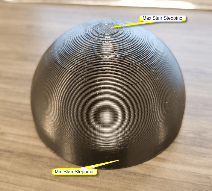
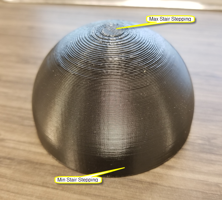
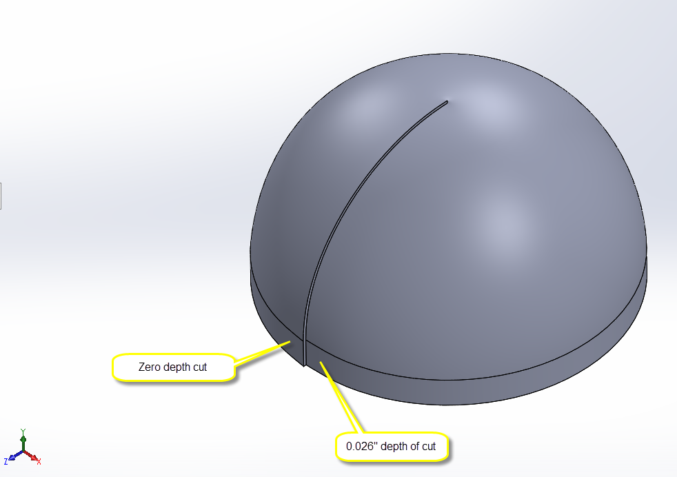
In order to look at as many different ranges of curvature and depths of cut as possible in a single part, I designed this helix cut dome in solidworks. The domed surface takes us from the least stair stepped printed surface on the sides to the most stair stepped on the top, covering a wide a range of scenarios that we might see coming off of an FDM 3D printer. The dome was 3” in diameter and printed at 0.013” layer height in black ASA material on our Stratasys F370 system. It was printed with sparse infill and five outer shell contours to ensure enough material was present to mill away as well as stand up under the cutting loads.
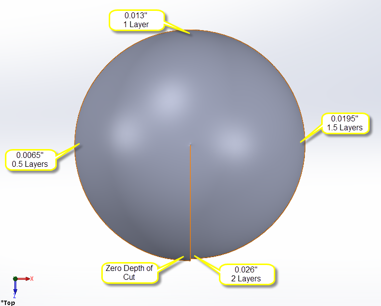
The reason this part was cut with a helix is to test a gradual change from a zero depth cut to one that would be 0.026” deep, which is the same as two of the layer heights this dome was printed in. This would give us a good range of depth of cuts in terms of layer heights to evaluate for surface quality. By looking at what angle our desired surface quality comes out at, we can determine that depth of cut from its ratio from 0-360 degrees compared to the depth of cut range from 0”-0.026”

The dome that was actually printed was one without a helix cut, just a simple 3” diameter dome. We will take our helix cut dome into our CNC software, SRP P
Finishing 3D printed parts on Roland Desktop CNC
Our newest addition to our Manufacturing Solutions family is the desktop cnc lineup of Roland machines. Having worked extensively with 3D printing technology in the past, one of the applications we were most excited about was taking 3D printed parts and finishing critical features/surfaces in our new CNC machines. 3D printers have come a long way over the years in terms of accuracy capabilities, but they aren’t quite at the level most CNC mills are capable of achieving. By starting with a 3D print and fiihsing on a mill we have the potential to leverage the speed and design flexibility of 3D printing with the high accuracy of CNC milling.
Here I will take you through the initial process we developed in order to surface a curved part with the intention of experimenting to see what depth of cut produced the most desirable surface finish. Future blog updates will follow our progress as we take a more in depth look at different operations such as more complex facing and boring out critical holes.
In order to look at as many different ranges of curvature and depths of cut as possible in a single part, I designed this helix cut dome in solidworks. The domed surface takes us from the least stair stepped printed surface on the sides to the most stair stepped on the top, covering a wide a range of scenarios that we might see coming off of an FDM 3D printer. The dome was 3” in diameter and printed at 0.013” layer height in black ASA material on our Stratasys F370 system. It was printed with sparse infill and five outer shell contours to ensure enough material was present to mill away as well as stand up under the cutting loads.
The reason this part was cut with a helix is to test a gradual change from a zero depth cut to one that would be 0.026” deep, which is the same as two of the layer heights this dome was printed in. This would give us a good range of depth of cuts in terms of layer heights to evaluate for surface quality. By looking at what angle our desired surface quality comes out at, we can determine that depth of cut from its ratio from 0-360 degrees compare to the depth of cut range from 0”-0.026”

The dome that was actually printed was one without a helix cut, just a simple 3” diameter dome. We will take our helix cut dome into our CNC software, SRP player. When finishing other parts, this is how the workflow should be handled. Design your part with the final dimensions in mind, same as any other part file. This will be the part you load into the SRP Player software. From there, you need to work backwards to add material to the part that will be printed in the 3D printing process, but milled away in the final cutting process. Have these two designs as either different configurations within the same file or as different files entirely. I named my files “Helix Dome-print.sldprt” and “Helix Dome-mill.sldprt” for example. At this point we are ready to print, but not quite ready to cut yet.
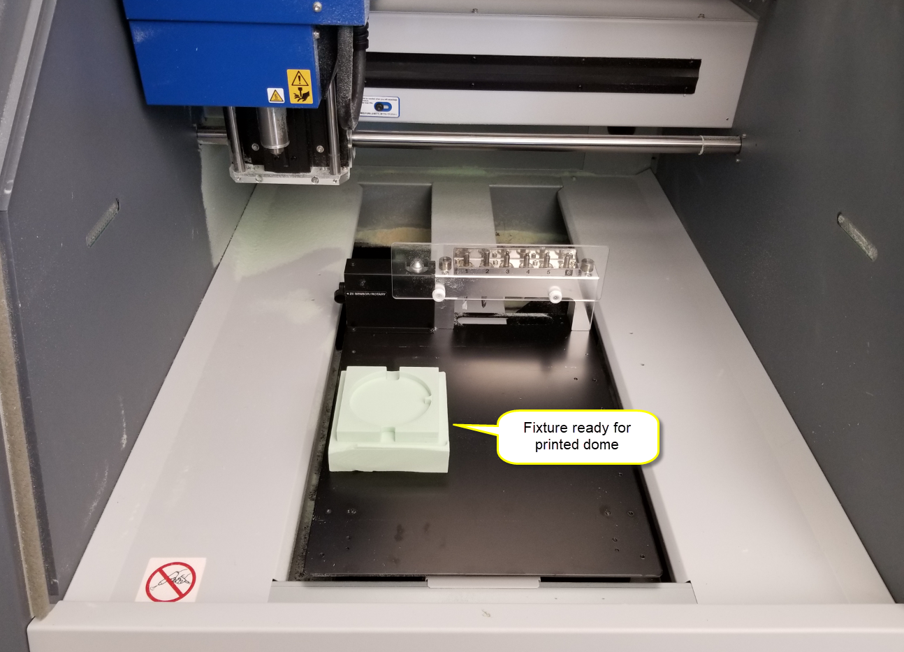
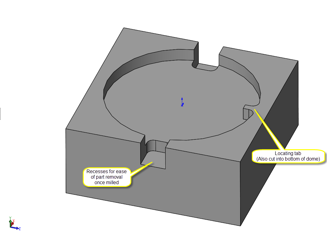
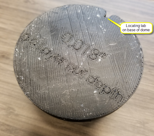
When CNC milling, a critical process step is workholding. We need a fixture to hold our dome securely and accurately while surfacing it. The following fixture was drawn up in solidworks and cut out of high density foam. If you take a little extra consideration during your fixture design, you can design for the tooling you intend to use to minimize cutting time. All features of this fixture were designed to be able to be cut by a ¼” endmill, specifically all corners were filleted to a 1/8” radius.


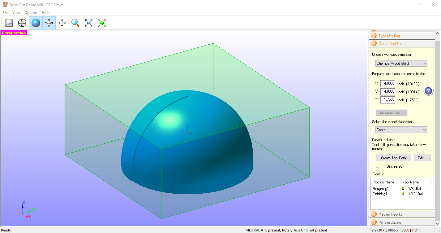
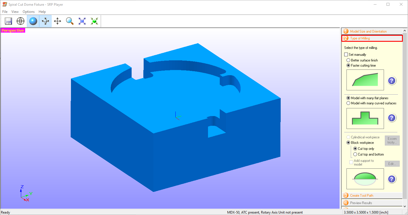
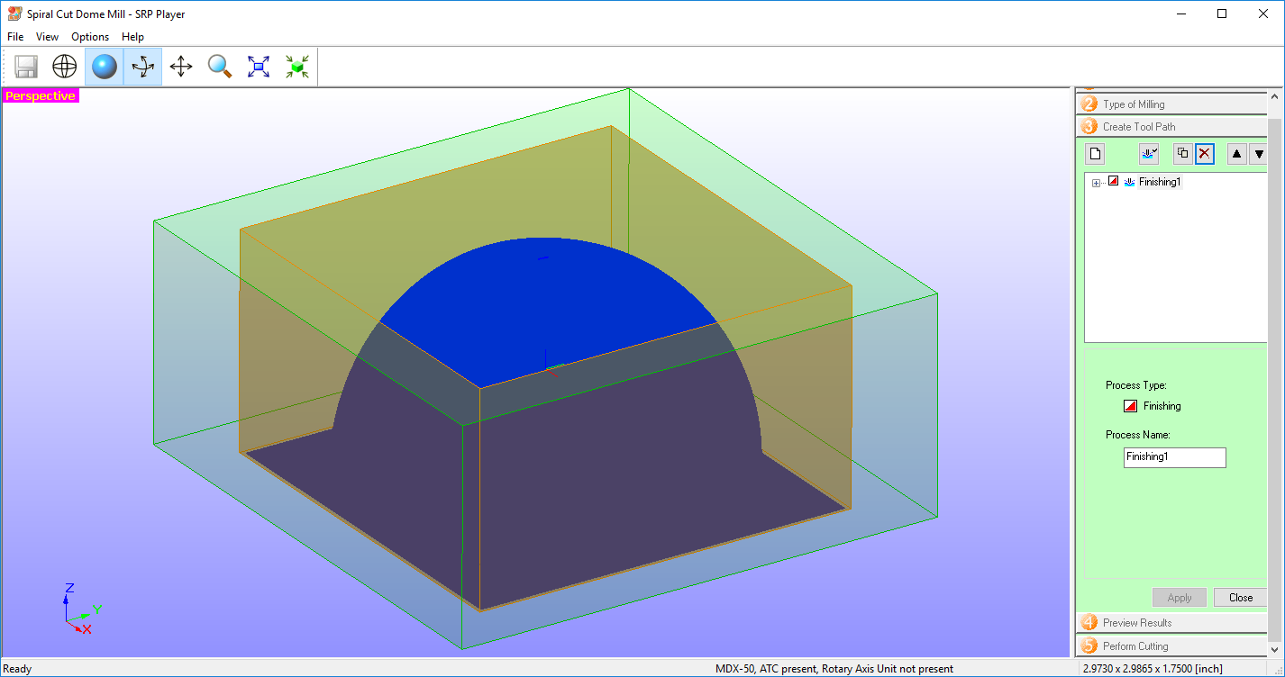
Here is a quick look at the SRP Player software interface. This fixture was cut with the default settings for chemical wood (soft) and with a ¼” flat endmill. The first step in the 5 step wizard is to choose your scaling and orientation parameters.

Next, a few questions about desired surface finish and part geometry.

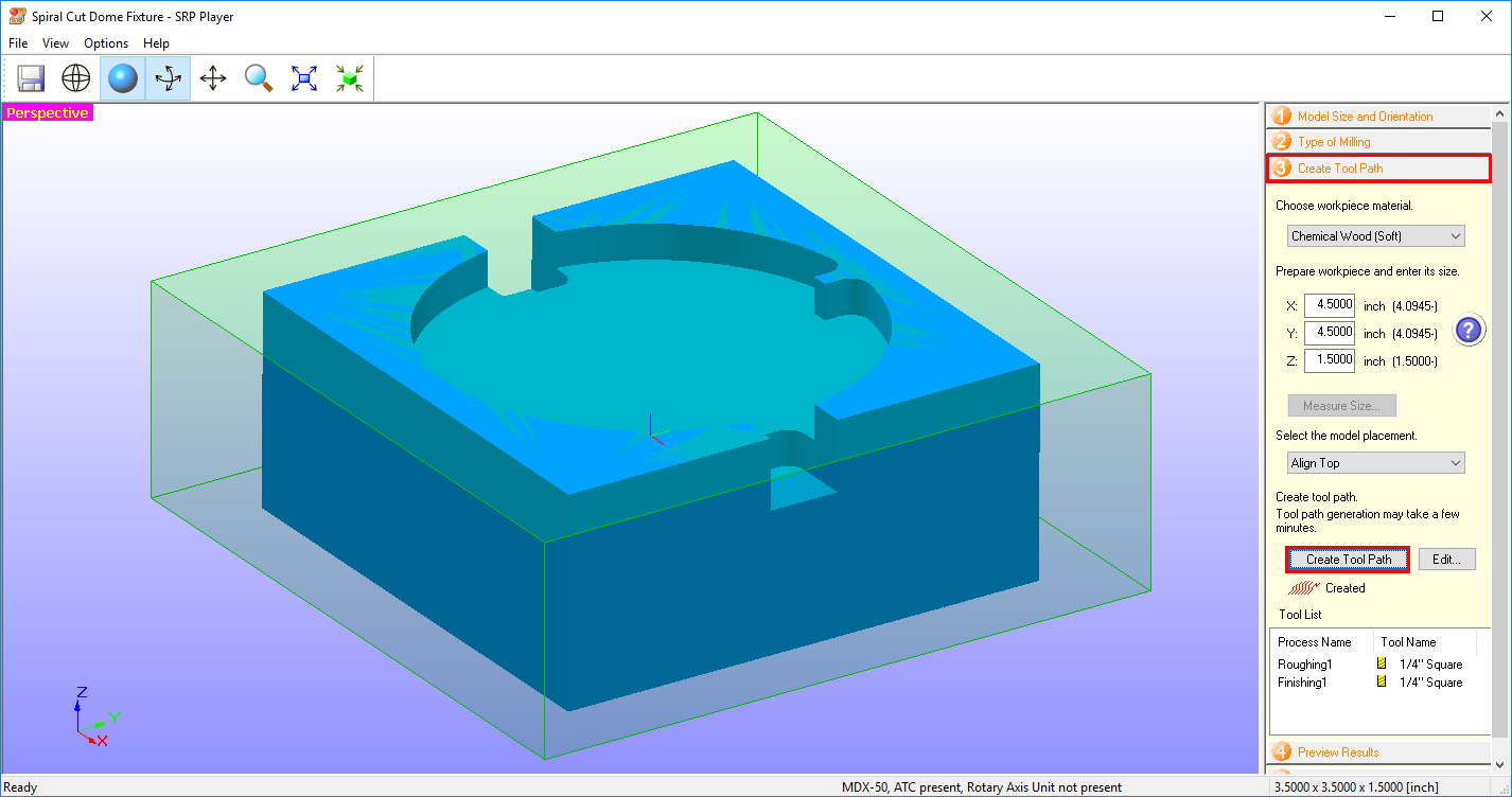
On to entering workpiece material information. All data is preloaded and chosen from drop down menus. This information is used to automatically populate tooling feeds and speeds, a very useful tool for inexperienced CNC users.

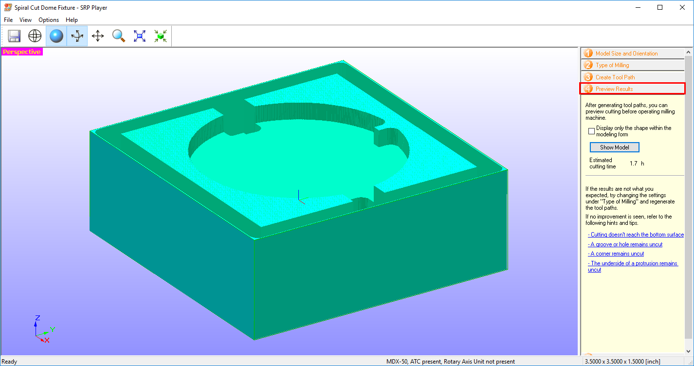
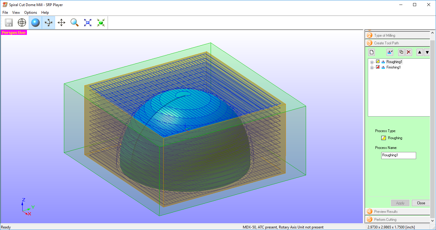
Last step before cutting is to preview the resulting geometry to make sure everything turns out as expected.
And here is our final result.
If we leave our dome fixture in the exact same spot as when we cut it, we wont need to change our origin when cutting our printed dome. This is a key step in this process because it would otherwise be impossible to set our origin accurately. Next we load the printed dome and generate the toolpaths needed to surface it.
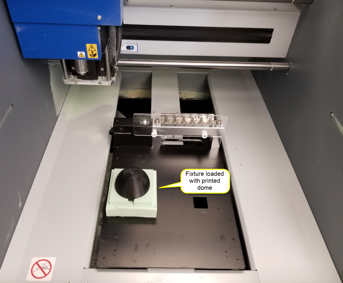
Here is where we need our “Helix Dome-mill.stl” file with the required final geometry for cutting. The main difference from the process outlined above is first to enter a phantom workpiece. No block will be loaded, only our printed dome. This works because our origin will be located at the peak of the dome, so workpiece sizing is irrelevant.
Once our toolpaths have been created, we are technically good to go. But if you notice, because we don’t actually have a block of material loaded, we will be cutting mostly air with these toolpaths. A quick and easy fix for this is to simply delete the roughing pass to eliminate the majority of the cutting time that we don’t even need.

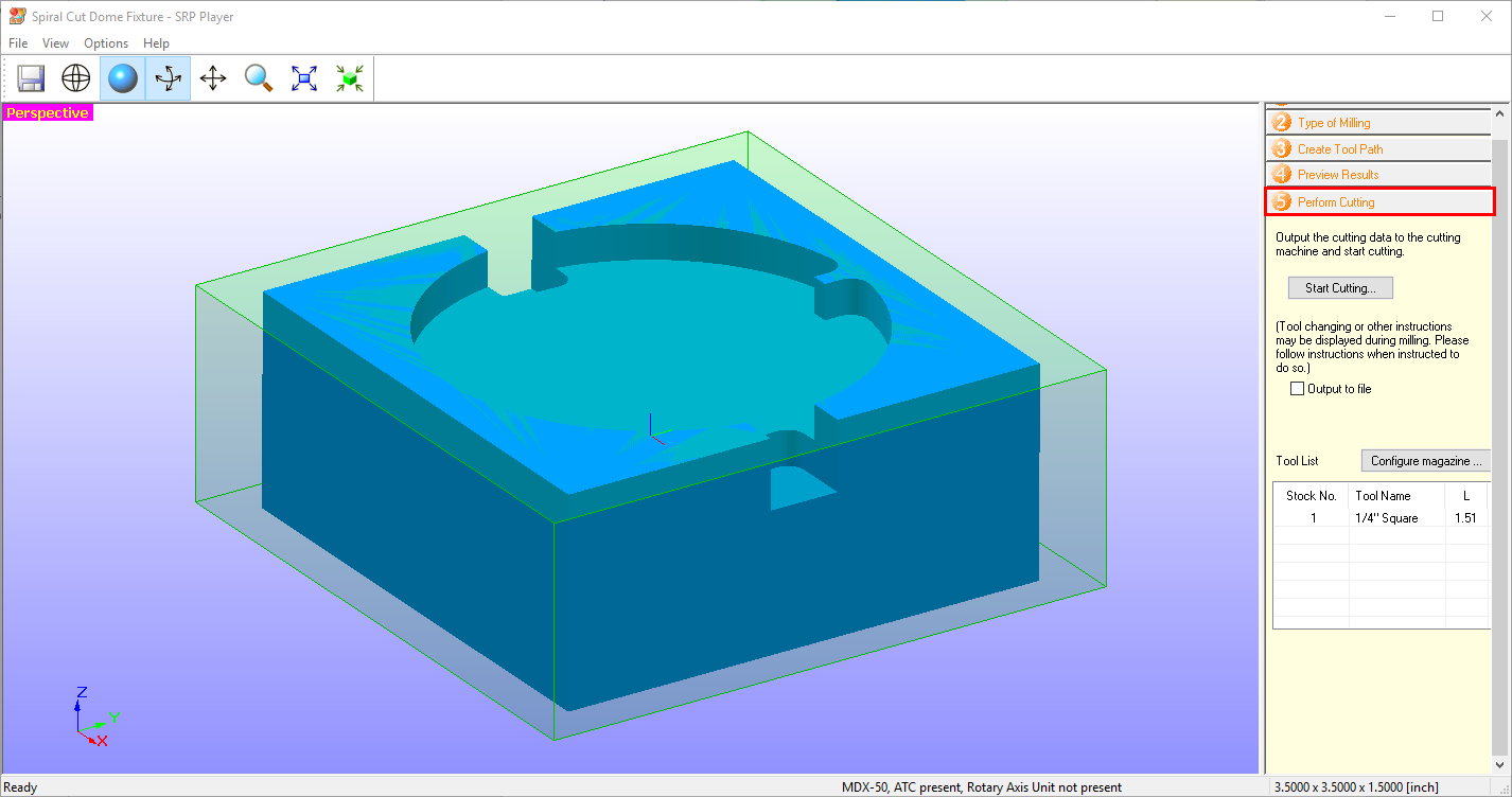
Now we are only cutting what we need to cut. At this point we’re ready to send the job to the mill.

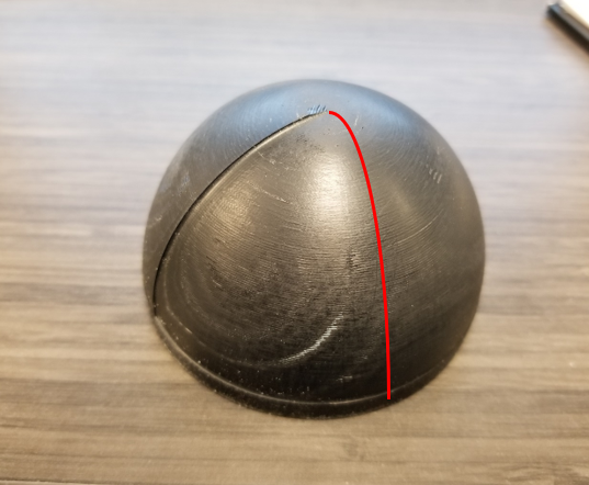
And here is our final result!
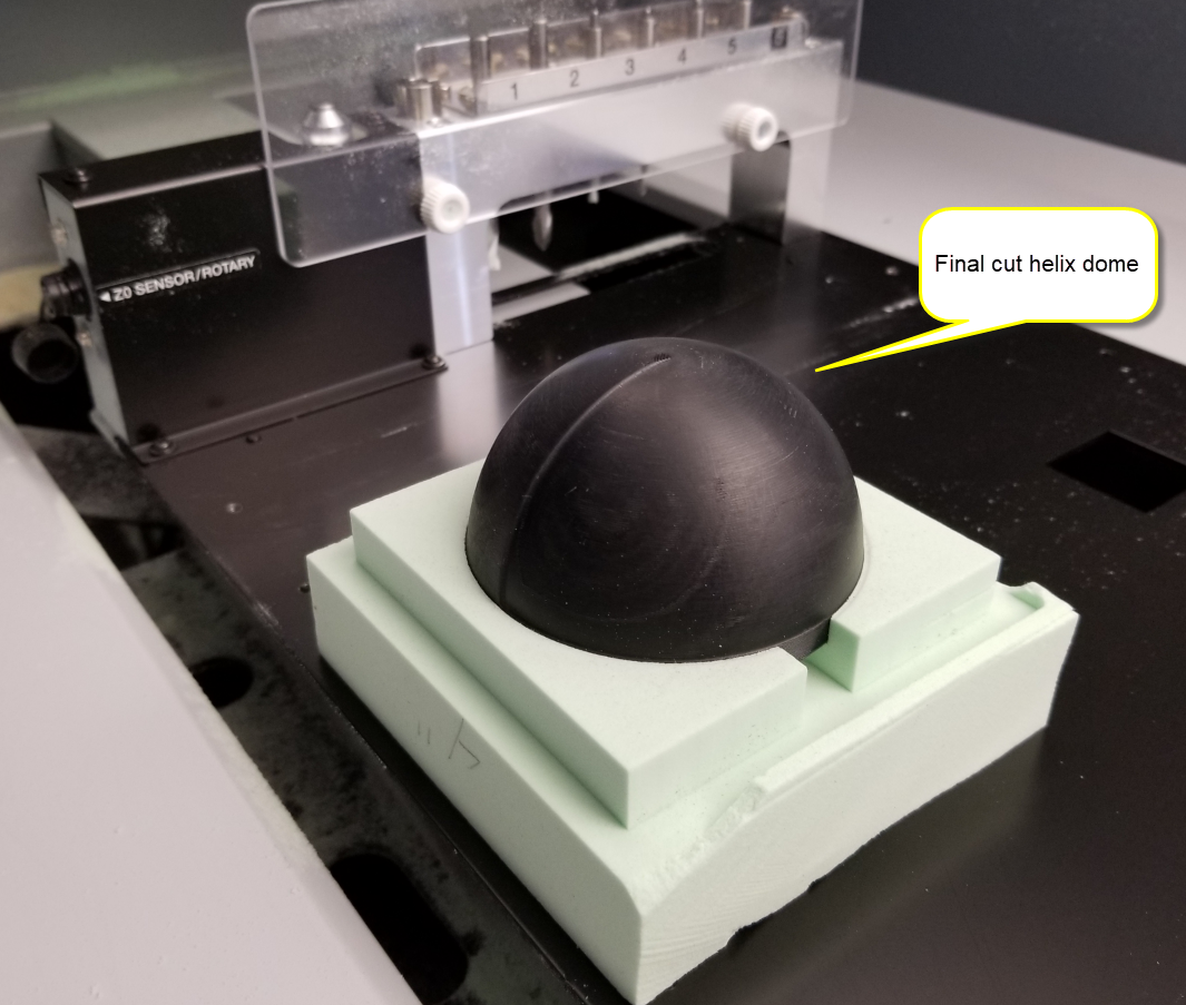
After close visual inspection, it appears the best general rule for surface finish may be a depth of cut of about 1.5 layer height (at about 270 degrees along the dome) . However there are definitely areas that have better surface finish in partial areas of curvature, but 1.5 layers definitely had the best over the entire range of dome curvature. So in summary, 1.5 layers as a finishing depth of cut is a good starting point, but you may need to experiment higher or lower depending on the severity of the curvature of your part.

layer. When finishing other parts, this is how the workflow should be handled. Design your part with the final dimensions in mind, same as any other part file. This will be the part you load into the SRP Player software. From there, you need to work backwards to add material to the part that will be printed in the 3D printing process, but milled away in the final cutting process. Have these two designs as either different configurations within the same file or as different files entirely. I named my files “Helix Dome-print.sldprt” and “Helix Dome-mill.sldprt” for example. At this point we are ready to print, but not quite ready to cut yet.
When CNC milling, a critical process step is workholding. We need a fixture to hold our dome securely and accurately while surfacing it. The following fixture was drawn up in solidworks and cut out of high density foam. If you take a little extra consideration during your fixture design, you can design for the tooling you intend to use to minimize cutting time. All features of this fixture were designed to be able to be cut by a ¼” endmill, specifically all corners were filleted to a 1/8” radius.
Here is a quick look at the SRP Player software interface. This fixture was cut with the default settings for chemical wood (soft) and with a ¼” flat endmill. The first step in the 5 step wizard is to choose your scaling and orientation parameters.

Next, a few questions about desired surface finish and part geometry.
On to entering workpiece material information. All data is preloaded and chosen from drop down menus. This information is used to automatically populate tooling feeds and speeds, a very useful tool for inexperienced CNC users.
Last step before cutting is to preview the resulting geometry to make sure everything turns out as expected.


And here is our final result.

If we leave our dome fixture in the exact same spot as when we cut it, we wont need to change our origin when cutting our printed dome. This is a key step in this process because it would otherwise be impossible to set our origin accurately. Next we load the printed dome and generate the toolpaths needed to surface it.

Here is where we need our “Helix Dome-mill.stl” file with the required final geometry for cutting. The main difference from the process outlined above is first to enter a phantom workpiece. No block will be loaded, only our printed dome. This works because our origin will be located at the peak of the dome, so workpiece sizing is irrelevant.

Once our toolpaths have been created, we are technically good to go. But if you notice, because we don’t actually have a block of material loaded, we will be cutting mostly air with these toolpaths. A quick and easy fix for this is to simply delete the roughing pass to eliminate the majority of the cutting time that we don’t even need.
Now we are only cutting what we need to cut. At this point we’re ready to send the job to the mill. Here we will be using a 1/16″ ball endmill.
And here is our final result!

After close visual inspection, it appears the best general rule for surface finish may be a depth of cut of about 1.5 layer height (at about 270 degrees along the dome) . However there are definitely areas that have better surface finish in partial areas of curvature, but 1.5 layers definitely had the best over the entire range of dome curvature. So in summary, 1.5 layers as a finishing depth of cut is a good starting point, but you may need to experiment higher or lower depending on the severity of the curvature of your part.