Flipped Angle Dimension in SOLIDWORKS
There has been a time or two in SOLIDWORKS when I have inserted an angle dimension in a sketch and found myself instinctively subtracting the initial numerical value from 360 degrees in my head. Sound familiar? Then let’s talk about some right-click options that will easily correct this issue for us.
Assuming the sketch is the desired shape and the two lines to be dimensioned have been selected, accept the on-screen dimension. We can change it after adjusting its Display Options. After all, the dimension isn’t wrong; it’s just displayed differently than what we had in mind. Hence the mental math.
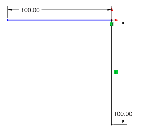
I’ve created a simple example to help illustrate the various outcomes of the Display Options; two sketch lines that stem from the origin. One has a vertical relation, while the other is free to move according to our intended angle dimension.
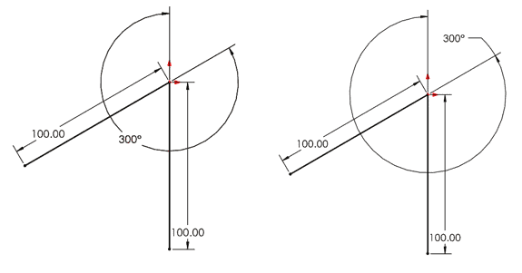
In this example, suppose I am after a 300-degree dimension. When placing the dimension, I instead see a 60-degree dimension. Digging a little deeper, let’s also say that I want the dimension to appear north of the Origin and reflect the greater distance between the lines, the Geometric Reflex Angle.
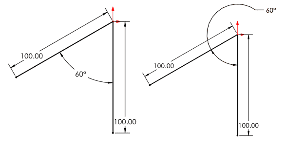
SOLIDWORKS allows for changing radial dimensions based on placement. While this capability addresses the issue most of the time, we are focused on the scenario that doesn’t play out like we expected. After placing the dimension, we unfortunately cannot simply drag the dimension to the other side of the origin. Above is an example of that failed attempt. SOLIDWORKS doesn’t operate like this, but I’ll include the images of this scenario throughout to emphasis this alternate dimension placement.
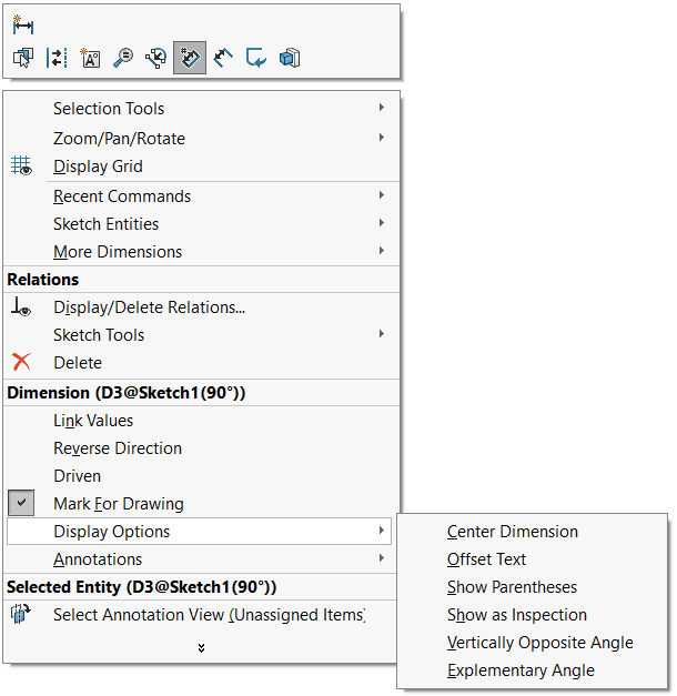
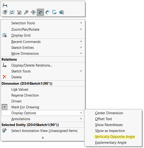
Exit out of the Smart Dimension tool to enable additional right-click options for the on-screen dimension. From the right-click menu, expand the line item for ‘Display Options’. Here we see a variety of selections at our disposal, but we are focused on just two.
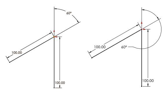
Let’s first take a look at the ‘Vertically Opposite Angle’ option. This selection will graphically display a leader from each line that extends through the Origin, in this case, to the other side of the sketch angle. Displaying a radial dimension with the ‘Vertically Opposite Angle’ display option will not change its numerical value. This option simply moves the dimension to reflect the Geometric Opposite Angle, which is the same value.
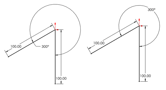
Moving right along, we now see the exact same dimension reflected using a different display option. Notice that in this scenario, the numerical value of the radial dimension has changed.
Jumping back to our mental math reflex, we know that 300-degrees is the value for the larger of the two angles present. (Did you catch the pun?)
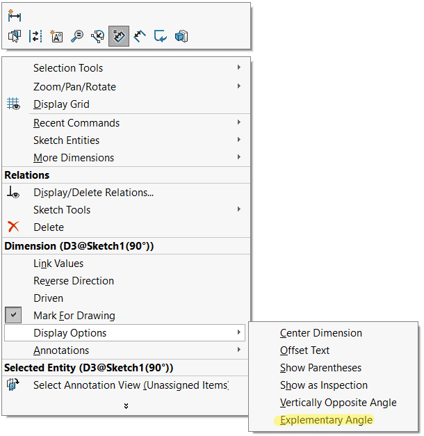
The specific name used for this reflex angle is ‘Explementary’. When selecting the Display Option for an Explementary Angle, we see our 60-degree radial value change to 300-degrees.
We are still in the ‘Vertically Opposite Angle’ display from the previous scenario so to reach our end goal of a radial dimension displayed above the origin and representing the larger of the two angles, we can select the ‘Vertically Opposite Angle’ option one more time.
As you might notice, neither of these two Display Options appear as being toggled on or off. This is due to the fact that these selections will always update the display of the dimension to reflect the desired change, regardless of the current scenario. There is no ‘this or that’ option. We are simply saying; “show the Opposite Angle of the current angle” and “show the Explementary Angle of the current angle.” Geometric rules are abided by, and we can flip back and forth all day long. While the lack of a toggle option can cause some confusion, play around with these two options until the desired result is achieved.
Gabriel Rodriguez
Application Engineer
Computer Aided Technology