Flow Simulation: Computational Domain Editing Part 1 – Symmetry
As with any engineering analysis project, efficiency is very important. If you use SOLIDWORKS Simulation for your structural finite element analyses (FEA) studies, you are probably familiar with the symmetry boundary condition, which greatly reduces the size of the problem and the time to solve it. Flow Simulation has a similar capability, and it is just as important to leverage this functionality because the computational fluid dynamics (CFD) method in use with Flow can take a while to solve for complex geometries. Symmetry affords a reduction in both solution time, which facilitates rapid design iterations, and the required computer memory. In my technical support role, I’ve helped several customers with their project setup who were surprised to learn of this functionality. Hopefully, this blog will raise awareness and make Flow Simulation project solutions more efficient for you too!
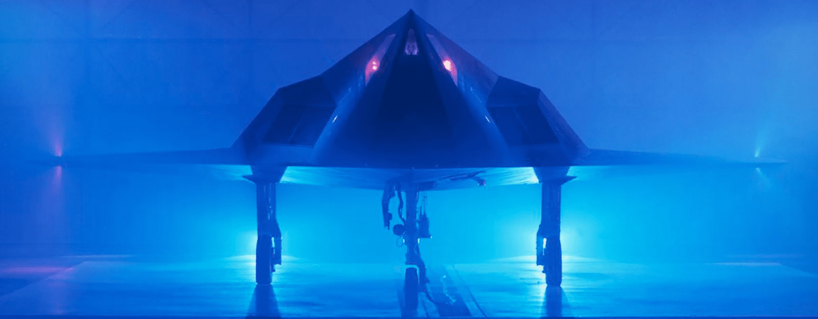
Aircraft are required to be symmetric to permit straight and level flight; the Lockheed F-117 Nighthawk stealth fighter, the world’s first “invisible” aircraft, is a great example to use for our discussion of symmetry in Flow Simulation. The jet was developed by Ben Rich, the innovative director of the Lockheed Martin Skunk Works project, and its first flight was on June 18, 1981. Naysayers saw the F-117’s unique profile and dubbed it the “Hopeless Diamond” in their prediction of its failure as a next-generation fighter aircraft candidate. History proved them wrong and, although retired in 2008, the F-117 would be the basis upon which subsequent stealth fighters, including the F-22 Raptor and F-35 Lightning II, would be designed.

https://www.lockheedmartin.com/en-us/news/features/history/f-117.html
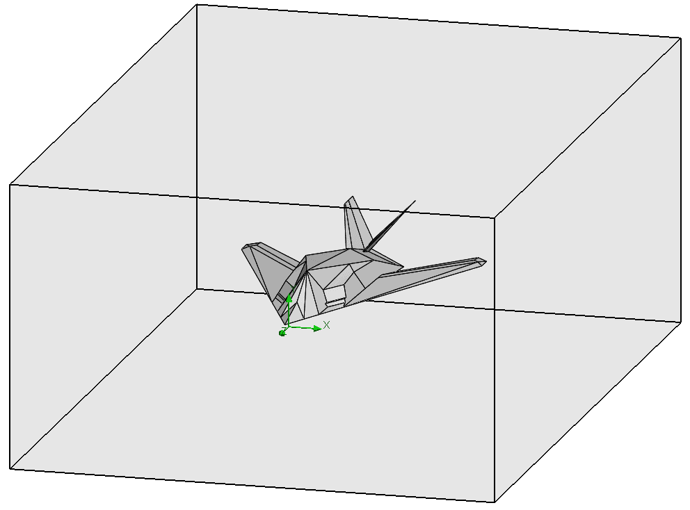
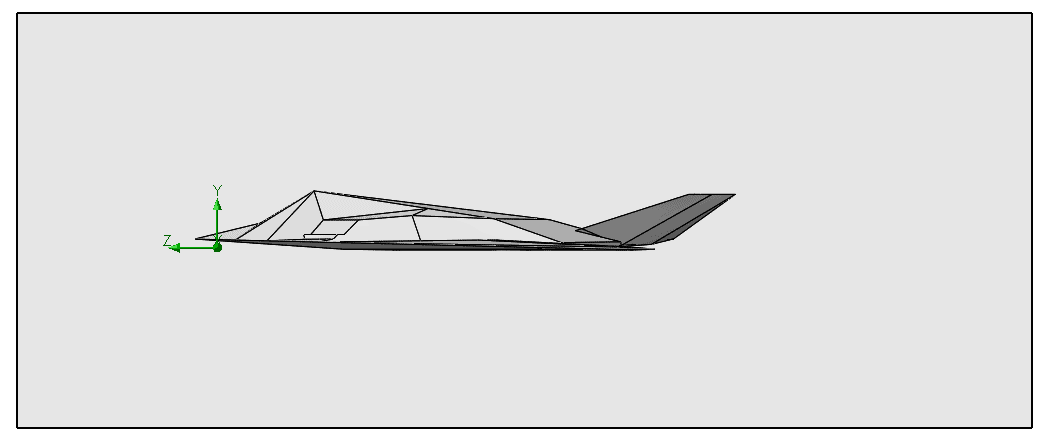
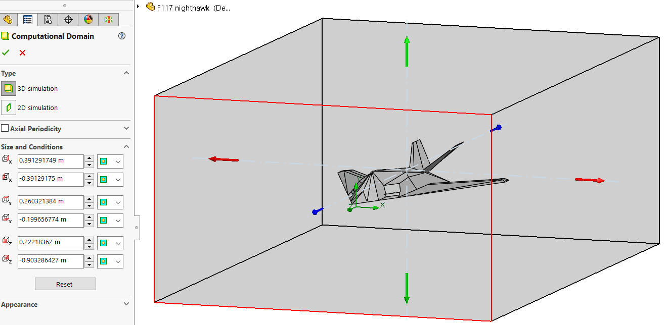
Whereas symmetry is applied in SOLIDWORKS Simulation as a boundary condition, for Flow Simulation it is affected by an edit to the computational domain, the volume of space considered by the solver that gets subdivided into small cells that capture the fluid, solid and boundary between the two materials. Here is the domain (the shaded grey box) for an external analysis of a scale model of the F-117. The domain was created automatically by the program upon completion of the project wizard and its size is based on several factors: internal vs. external analysis type, model dimensions and initial flow conditions. With straight and level flight the initial flow is in the -Z direction and you can see from the side view that the domain is slightly extended past the model in that direction to allow for flow transition past the jet. As always, the domain can be extended in any direction if additional distance for flow development is needed.
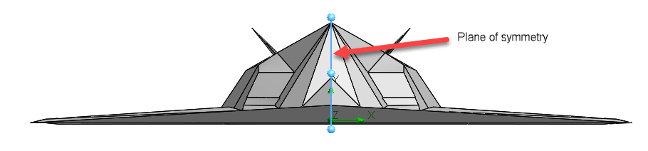
The requirement for using symmetry is that both the geometry and flow conditions are symmetric. Simulation of an aircraft meets this requirement and a symmetry plane along the centerline of the fuselage can be used.
https://www.lockheedmartin.com/en-us/news/features/history/f-117.html
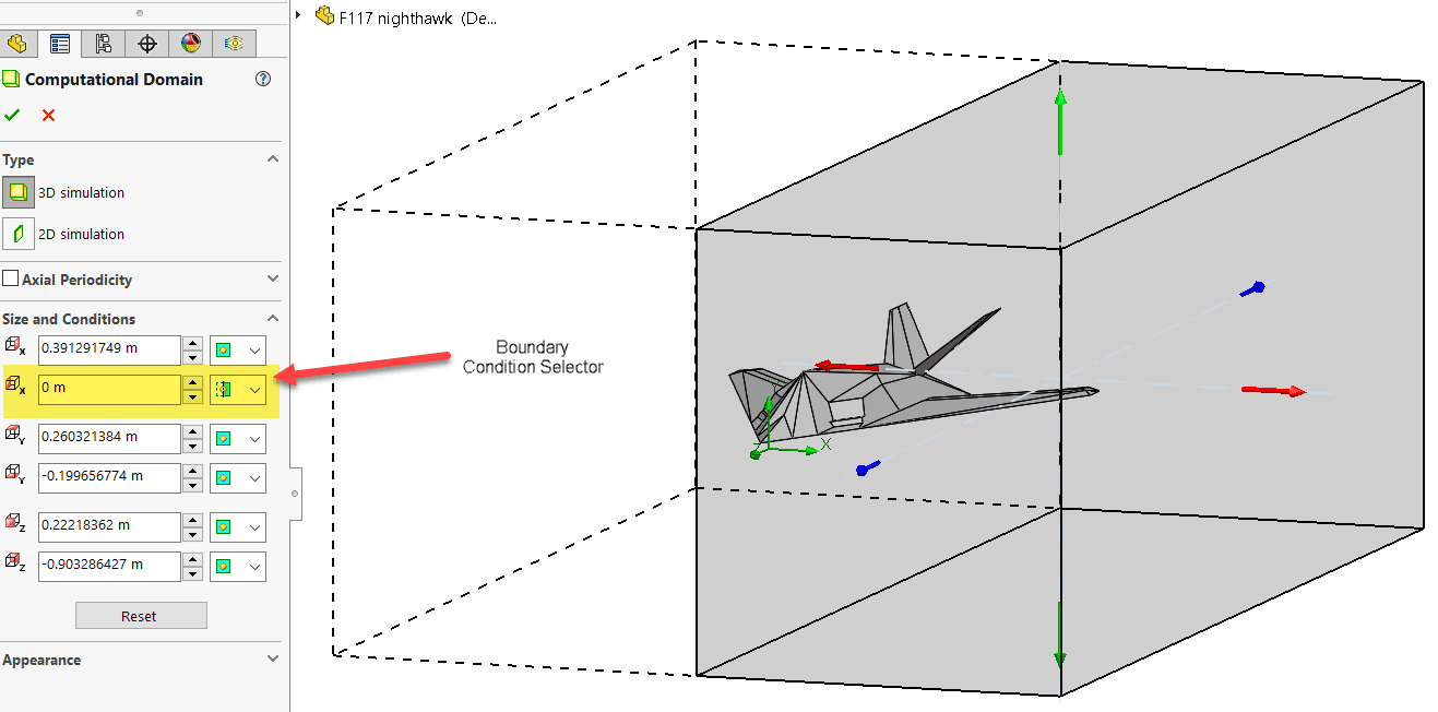
To make this change for the project, right-click the computational domain icon in the project tree and select “Edit definition”.
Then, simply zero out the X-min dimension and switch the domain boundary condition from “Default” to “Symmetry”. Notice the dashed-line representation of the new domain indicating that this part of it will be captured as a mirror image of the domain that is actually solved.
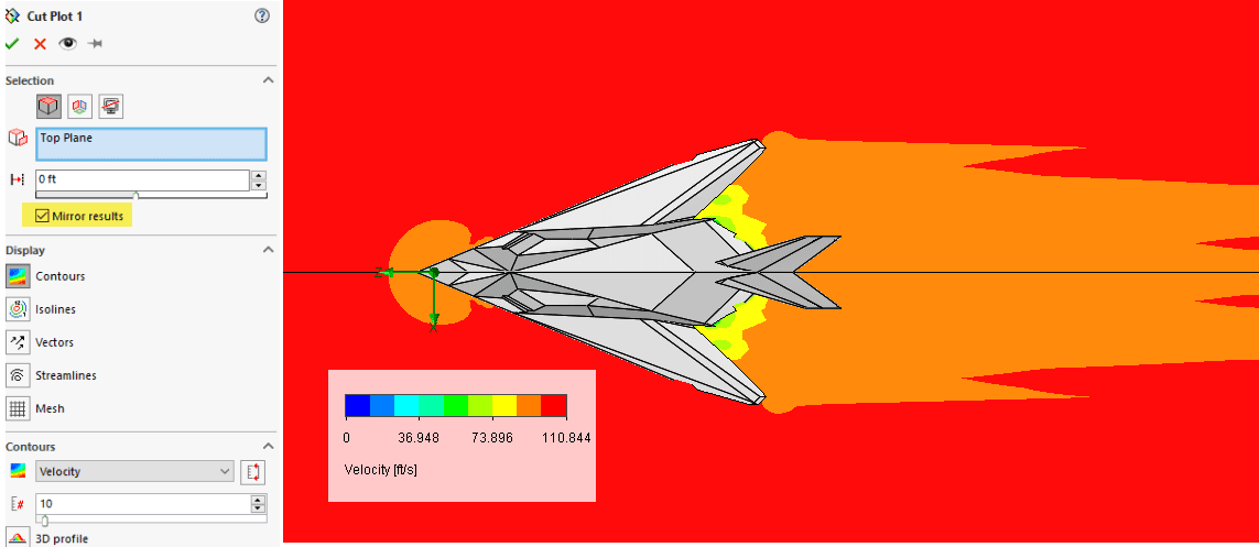
Results are generated twice as fast as a solution using the full domain. For some results output types, the solution can be mirrored to the other side as shown in the cut plot of velocity below.
There’s even more that we can do with the computational domain in Flow Simulation – look for future CATI blog posts on the subject. Thanks for reading!
Kurt Kurtin
Technical Manager, Simulation Products
Computer Aided Technology, LLC