How to Automate Bolted Connections in the 3DEXPERIENCE Platform!
The 3DEXPERIENCE Platform is an extensive solution platform with multiple roles and software applications that can be a great compliment to SOLIDWORKS desktop. Among the many great applications on the 3DEXPERIENCE Platform, are the simulation roles: Structural Performance Engineer (SFO) and Structural Mechanics Engineer (SSU). Both simulation roles contain numerous simulation applications to solve advanced Finite Element Analysis (FEA) problems. In today’s blog I am going to show some automated meshing techniques on the 3DEXPERIENCE Platform that make applying connections very easy!
The first step is to export our SOLIDWORKS part file into the platform. The dataset we are using is two plates that are connected via numerous bolted connections; the bolted connections must be applied in our FEA scenario. The top and bottom views of the CAD model are shown in Image 1 below.
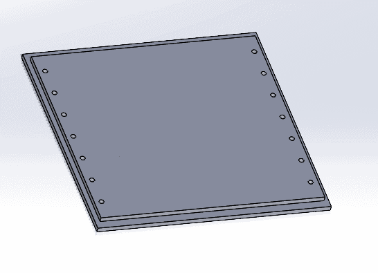
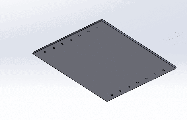
Image 1: SOLIDWORKS Dataset
The process to import files into the 3DEXPERIENCE Platform is easy and can be done either via the direct import option or through the SOLIDWORKS connector. For more information on how to import files into the platform, check out my colleague’s blog that goes over both the connector and direct import option in more depth. In our case I am going to utilize a direct import within the platform itself (See Image 2) to bring the file into the platform.
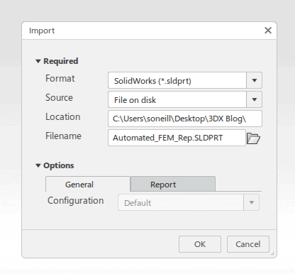
Image 2: Direct Import of SOLIDWORKS Part File
Once the file is imported into the platform, we can go through the process of setting up our simulation study. In our case we are going to focus solely on the automated meshing options, thus the technique I am showing can be applied with either the SFO or SSU roles. Once we are active in either an SFU or SSU simulation scenario, we can go through the process of meshing our system. To mesh our system in the platform we need to create a finite element model (FEM) representation of our cad geometry. We can create a FEM representation through selecting the Automated FEM option and then selecting the Advanced FEM option as shown in Image 3.
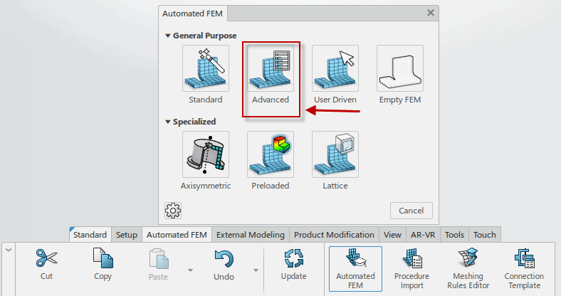
Image 3: Automated FEM
In our case the reason we want to utilize an Automated Advanced FEM option is because we have numerous bolt holes where we need to apply a connection, and the advanced option automates this process. If we do not use the advanced FEM option, we will spend much more time manually creating all the bolted connections. After clicking on the Advanced FEM Icon, the advanced settings dialogue will pop up (Image 4).
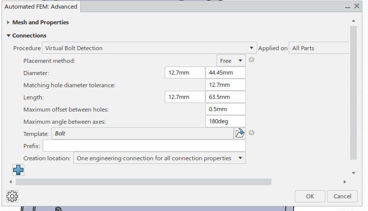
Image 4: Advanced FEM Options
Within the advanced FEM options there are options for automating the overall mesh, and also options for automating the connections (Image 4). In our case we want to automate all bolted connections in our model, so we select the bolt connection option. Within the connection’s options, we can enter the settings to search for all the bolts in our model. It is important to key in values within the max and minimum values of the bolt sizes. After all these options are entered, we hit ok and update our model to show our updated mesh (Image 5) with bolted connections.
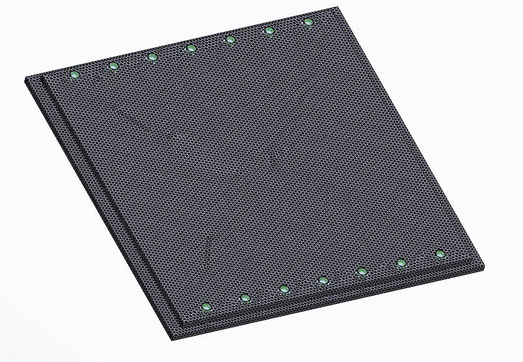
Image 5: Meshed Model with Bolted Connections
Without utilizing this automated bolt option, the process to create bolt connections would have required us to manually specify each hole edge within our entire model. Thus, the automated method saves us significant time while still applying all accurate connections in our system. The other great thing about the automated method is that it still creates separate bolted connections in our design tree, and if we ever need to edit or change an individual connection, we can do that by editing directly in our tree (Image 6).
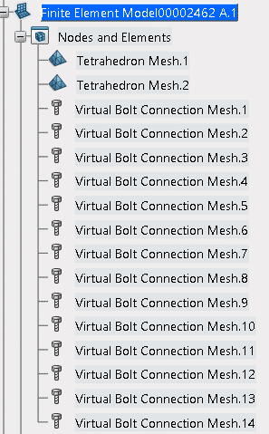
Image 6: Bolt Connections in Tree
I hope you can use this tip the next time you mesh an assembly or part file on the platform! If you have any further questions on the 3DEXPERIENCE Platform, please reach out to us to see how you can utilize the 3DEXPERIENCE Platform to streamline your design processes.
Drew Buchanan
Sr. Application Engineer Specialist, Simulation
Computer Aided Technology