Import CMM Measurements Into SOLIDWORKS Inspection Professional
After obtaining your measurement values from your Coordinate Measuring Machine (CMM), how do you reconcile them with the expected values from the drawing? With SOLIDWORKS Inspection Professional, you can import them into your Inspection project and they will map to the appropriate characteristics.
First, be sure you have the option turned on in the standalone version of SOLIDWORKS Inspection Professional.
After opening Inspection, go to Home > Options > General > Add-ins > Measurements Input and CMM Data Import.
Next, open your completed Inspection project and look for the CMM Data Import tab on the right of the screen. Click the tab and pin it open.
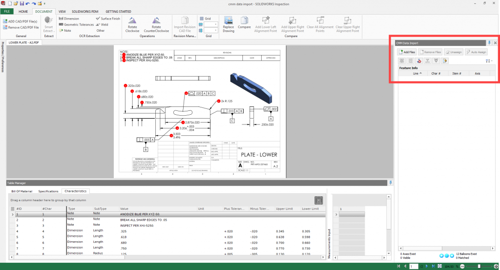
Click ‘Add Files’ and open the file exported from your CMM. SOLIDWORKS Inspection can open files from almost any CMM program, including PC-DMIS, Calypso, Faro and more. Templates are provided to map measurements from your CMM source to the Inspection project.
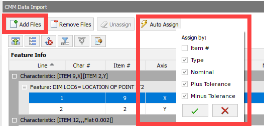
Once the file is added, use the ‘Auto Assign’ button to have Inspection attempt to map all the measurements in the CMM file to the Inspection project. You can choose one or more categories for Inspection to use, including Item #, Type, Nominal, Plus Tolerance, and Minus Tolerance.
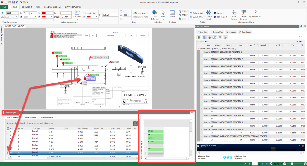
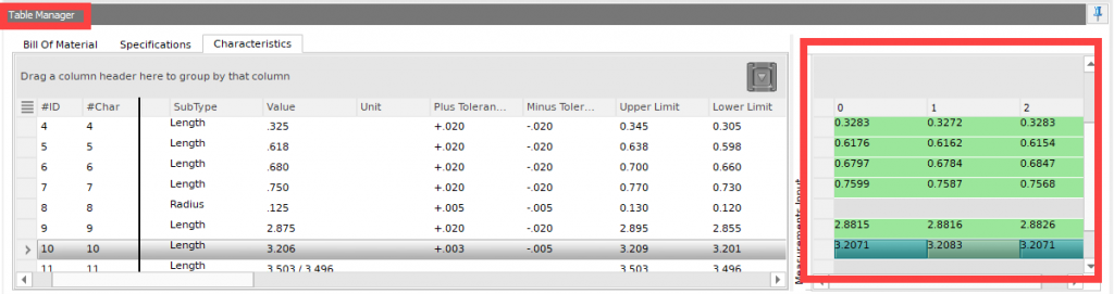
You will see the results in the Table Manager window, complete with color coding in the table and on the dimensions in the drawing that are connected to those characteristics. Green = Pass, Yellow = Marginal Pass, Red = Fail.
If a characteristic on the drawing is gray colored, the Auto Assign was not able to make a match and you will need to map those manually. For example, Characteristic 10 is missing a result below.
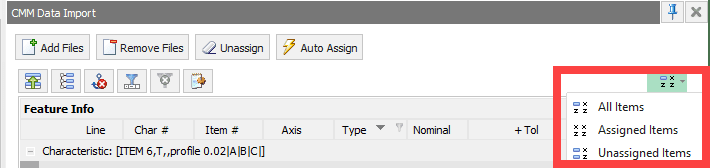
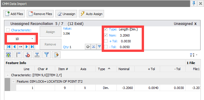
In the CMM Data Import window, we will filter on Unassigned Items and look for measurements that we can map to this characteristic.
Choosing Characteristic 10 in the drop-down shows Item 9 from the CMM measurement data aligns with the Type and Nominal, but not the Tolerances.
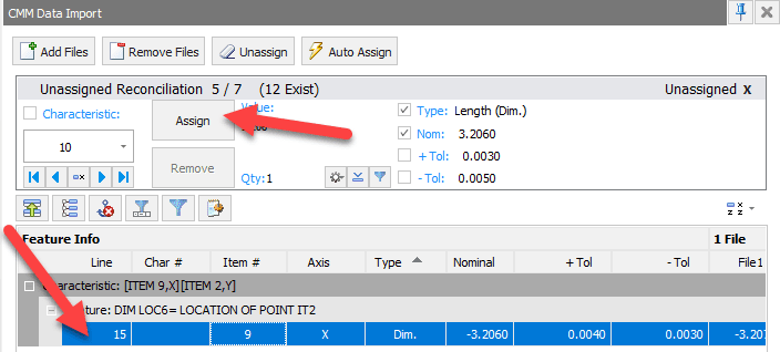
We know this should be mapped to Characteristic 10 in the Inspection Project, so we select the row in the Feature Info window and then ‘Assign’ from the Unassigned Reconciliation portion of the window.
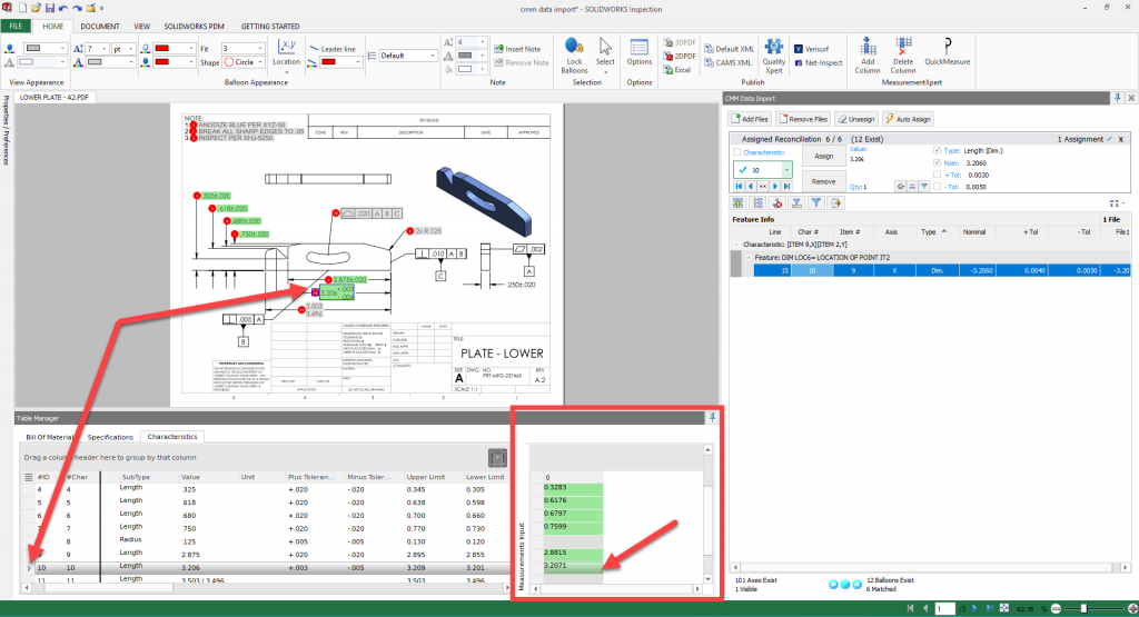
The Table in the Table Manager window reflects the update with the assigned value and color coding.
If more than one set of measurements were taken, all you have to do is click the ‘Add Files’ button again and choose the additional files from the CMM output. Inspection remembers the manual mappings and displays the additional columns of measurements in the Table Manager.
From here you can publish an Inspection report to share the results with your team.
If you are reconciling CMM output to your Inspection Drawing, check out SOLIDWORKS Inspection to see how it can greatly reduce the amount of time it takes to perform this task.
Be sure to subscribe to the CATI blog to get a weekly digest of all our blog posts.
Chris Snider
Sr. Mgr. Field Technical Services – East
Computer Aided Technology, LLC