Imported Geometry | It Doesn't Have to be Hard to Work With
Brennen here, back with some more imported geometry. Have you ever had some simple purchased parts that you’d like to incorporate into your design, and so you read over the dimension specs and create the right cut-out for the part? From bearings to gears to O-rings, the type of purchased part can vary widely, and no matter what you’re using, this process can end up being painful and tedious.
Thankfully, nowadays many major part suppliers let you download a 3D model of their part. This often comes in the form of a STEP file. Sometimes suppliers will even publish a SOLIDWORKS part file instead of a STEP file. Along with that, there is a variety of parts included in the SOLIDWORKS toolbox, and some suppliers have even created add-ons or design libraries so you can access their files directly from within the SOLIDWORKS environment.
Using Imported Geometry in Your Assembly
Regardless of whether you’re fortunate enough to have a real SOLIDWORKS part, or are stuck working with a STEP file, we can easily use those files to help us create our design. To get started, open up your imported file, and save it as a SOLIDWORKS part. Don’t worry if your feature tree is full of “Imported” geometry, and don’t worry about feature recognition.
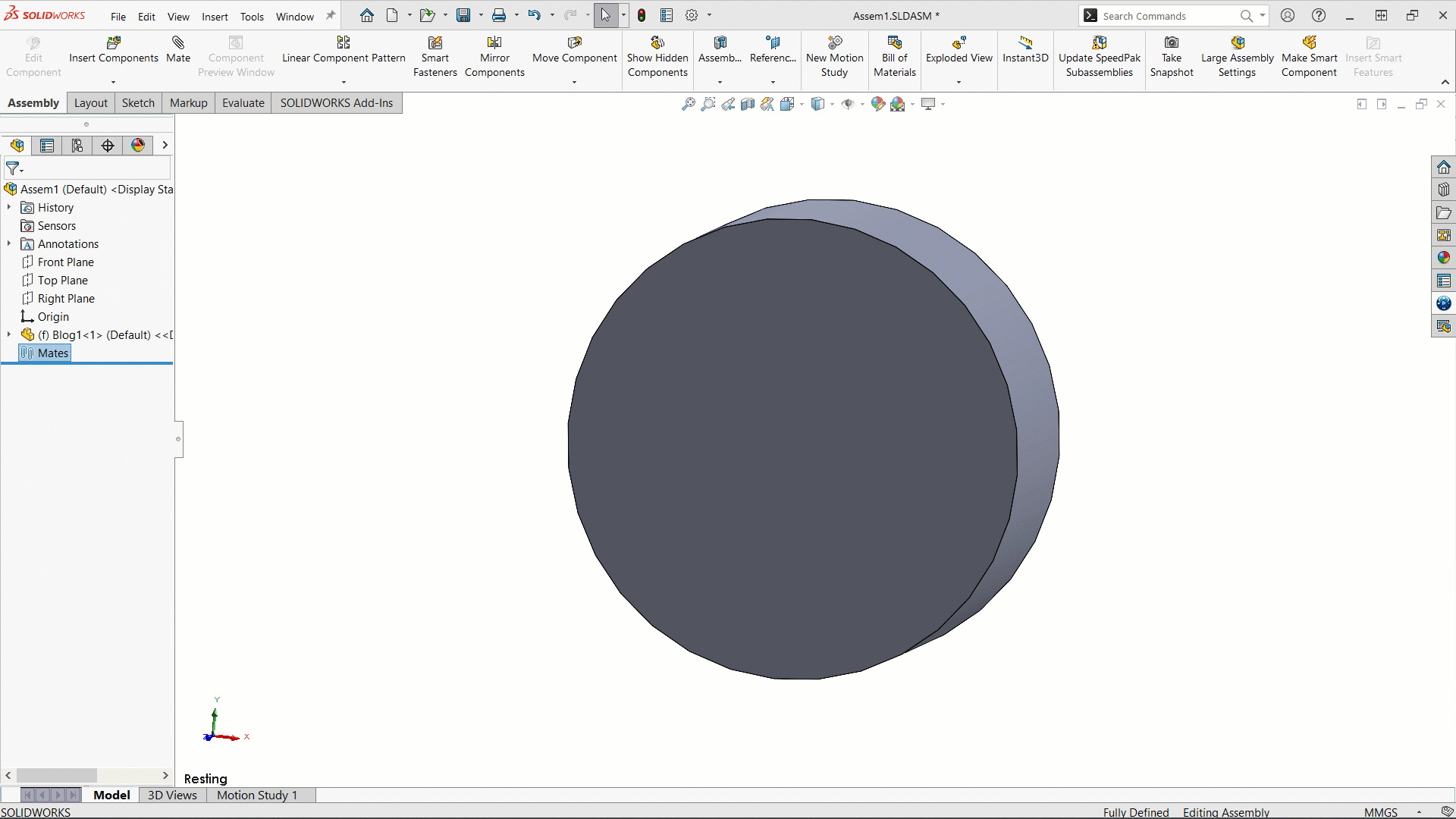
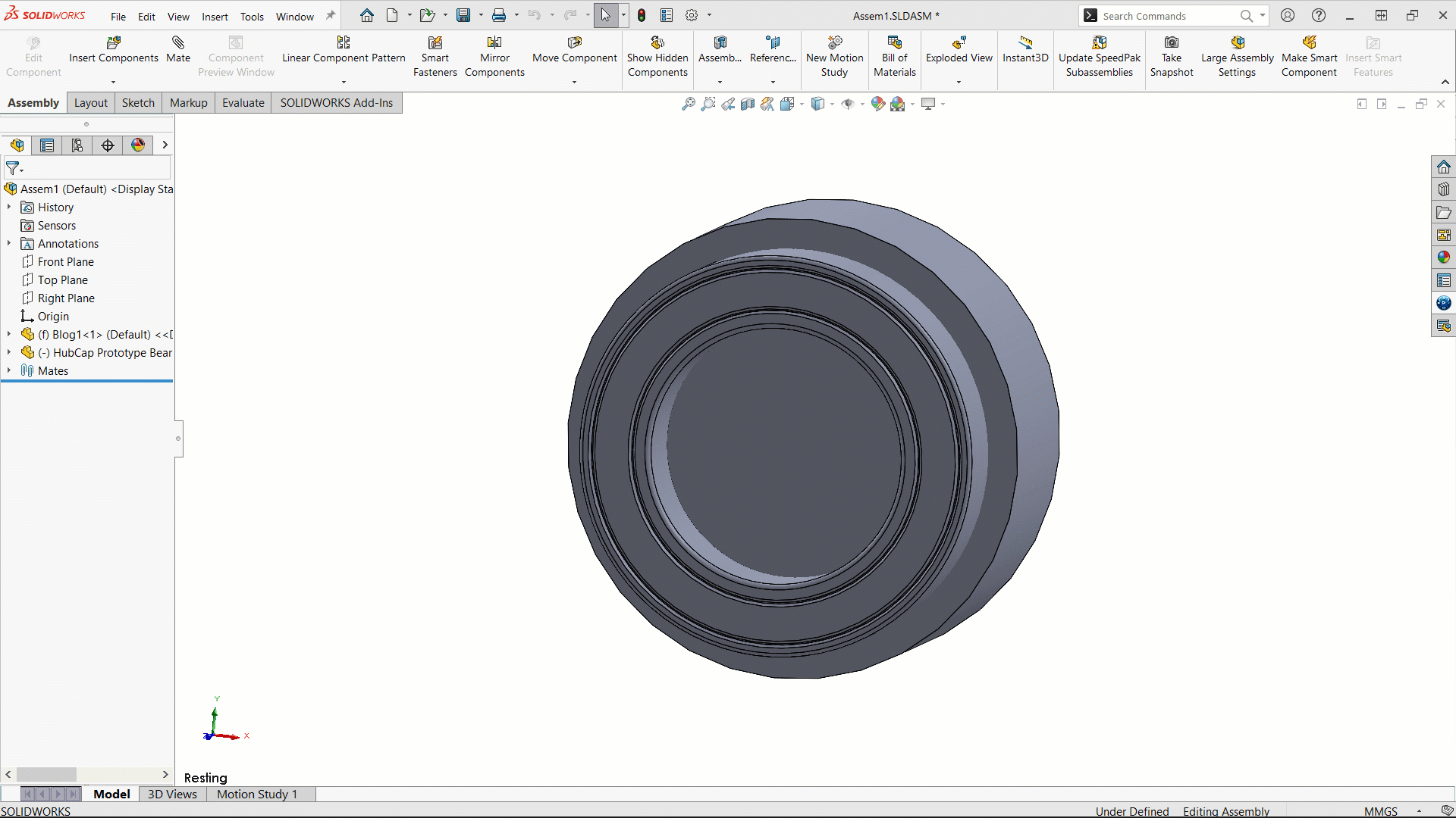
With your assembly open, simply add in the imported geometry you want to work with, and we’re off to the races. I encourage you to save the file you’re using with the rest of the assembly so when SOLIDWORKS tries to track it down for in-context references, it doesn’t have any difficulty. Once you’ve got your model in the assembly, the next step is to position it where you’d like it to end up using some simple mates.
Import the Geometry
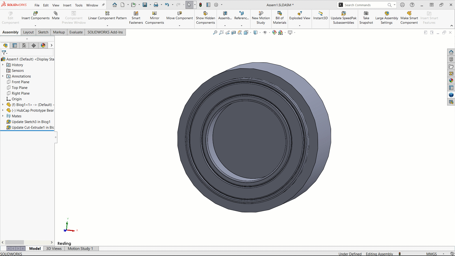
From here, we can start using the imported geometry to create new geometry. Whether it be a boss or a cut, we can use the edges of imported geometry to control its shape. To begin, select the part you’d like to edit, and select “Edit part”. Next, you can use relations & or convert entities to grab the desired geometry and add it into a sketch. With your sketch finished, you can create whatever feature you need, using the geometry.
Final Mates
With your feature created, you can now add any more required mates for your design. This could be as few as just one more, or it could be a handful.
Parametric
Thanks to SOLIDWORKS’s parametric nature, the in-context changes propagate out to the part level. This creates an in-context relationship between the two parts.

Breaking the link
Sometimes those in-context references can be a headache, and maybe you just needed one briefly. Thankfully, we can always break the link. Be careful though, as breaking the link is permanent. In order to reestablish the link, you will have to go through some of this process again.

That’s the basics of doing some in-context modeling, whether you have a genuine SOLIDWORKS part or some imported geometry. Stay tuned for part 2 where I talk about design changes with in-context parts and go over how to fix some errors including mates and relationships.
Brennen Sands
Application Engineer
Computer Aided Technology