Let’s Go Bowling with SOLIDWORKS Motion
With the COVID-19 pandemic still upon us, I decided that I needed a diversion, so I decided to go bowling – virtually! I’m admittedly a terrible bowler so playing this sport within the security of my computer saved me the embarrassment I would have otherwise endured.
Way back in 2011, SOLIDWORKS introduced the ability to use PhotoView 360 rendering together with SOLIDWORKS Motion for the upcoming 2012 release. As part of the 2012 Beta program I developed and rendered the simulation you see below. (If interested, access the 2021 Beta program.) It was a great exercise to refresh my CAD modeling techniques, implement camera views and dig deeper into the rigid-body dynamics functionality of SOLIDWORKS Motion.
Bowling aficionados hailing from the boroughs of NYC will recognize this “Brooklyn Strike”. If this term is unfamiliar, you are, like me, probably from the South! I give credit to a kind commenter on the Beta forum for pointing out the name.
The Professional Bowlers Association (PBA) website clarifies that “a ‘Brooklyn’ refers to a ball that crosses over to the other side of the head pin opposite the side it was thrown (i.e., a Brooklyn strike hit the 1-2 pocket for a right-hander).” More wisdom from the web says this “crossing over” originated as a reference to someone going from Brooklyn to Manhattan.
Back to the topic at hand… It was very satisfying to open this file for the first time in several years and take a few turns again! A simulation of this type involves defining the gravity direction, creating 3D contact sets between components and setting initial conditions for the bowling ball.
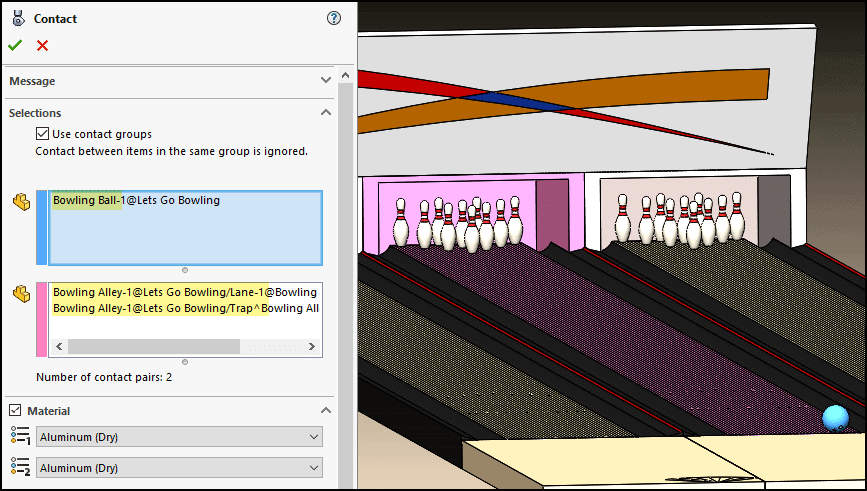
Contact sets are crucial and are determined by the possible component interactions and their materials. The first set is between the ball and lane components (lane surface and ball trap). The materials selected here contain the impact and friction characteristics while mass properties come from the material originally set for the parts. In this case, the relatively hard aluminum material was ultimately used to properly handle the point contact involved and prevent unrealistic penetration of the ball into the lane surface.
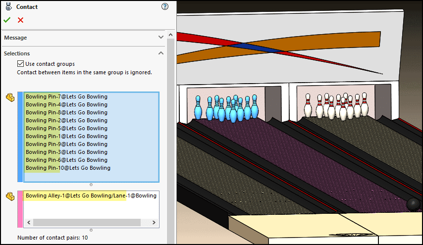
The second contact set is between the lane and pins. Aluminum is also used here due to the very small contact area of the pins.
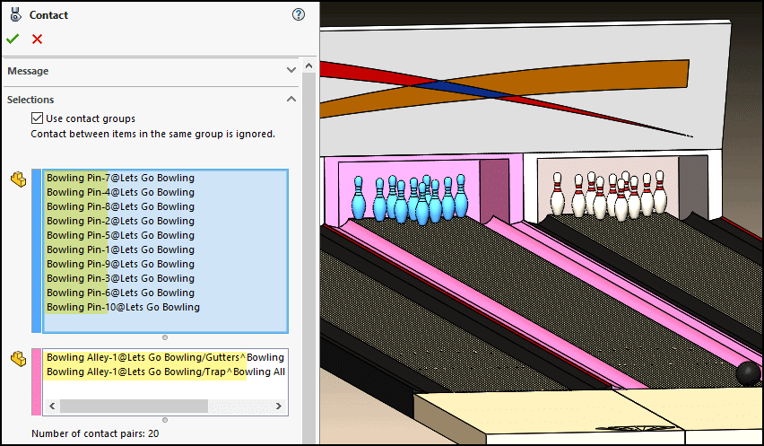
The third contact set is between the pins, gutters, and lane trap using acrylic and aluminum materials. Note that my virtual bowling skills are such that I don’t need a contact set between the ball and gutters because I don’t throw gutter balls – as far as you know!
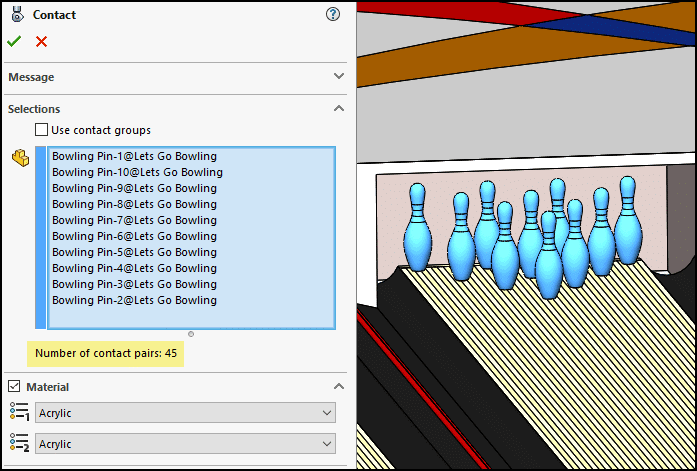
An acrylic material contact set accounts for the interaction between the pins. The number of contact pairs is 45 for this group to account for all the possible combinations.
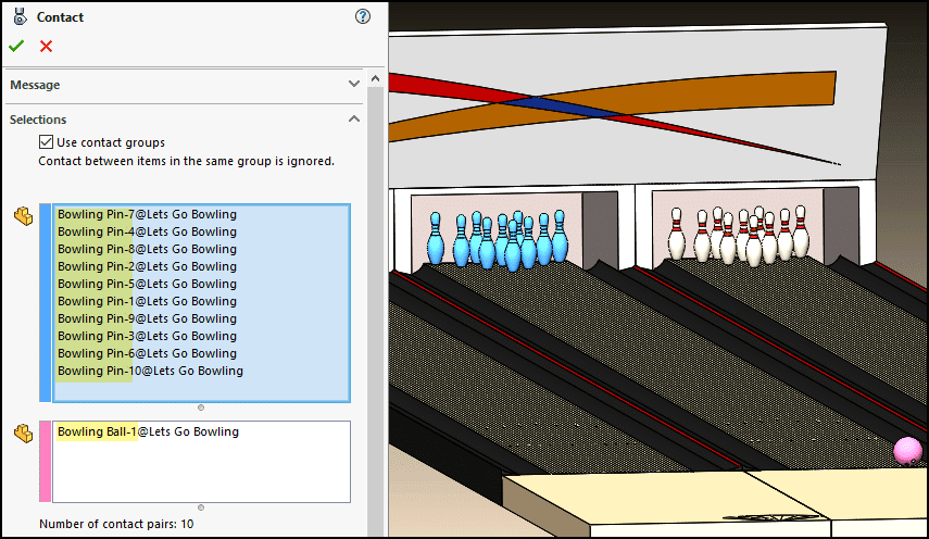
Finally, a contact set with acrylic-on-acrylic material is used between the ball and pins.
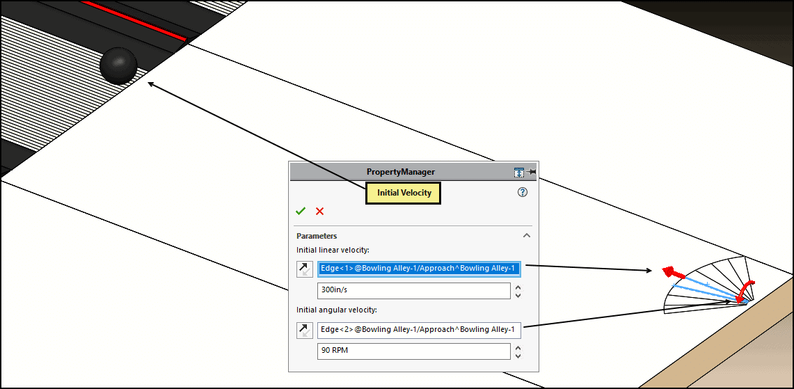
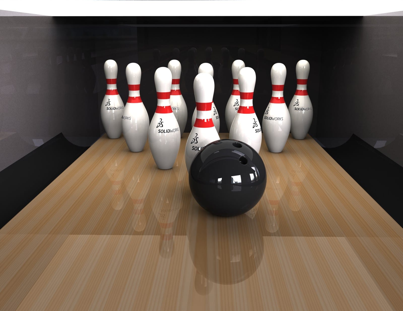
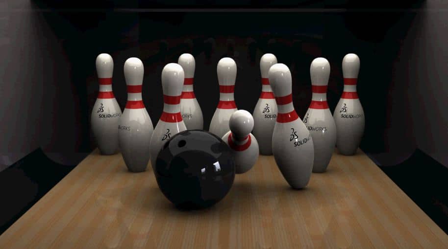
For the setup of the ball initial conditions, I used a reference sketch on the surface of the lane in the delivery area. Several lines allow me to deliver the ball in different directions and apply spin. Here, I’ve positioned the ball as shown and started it straight down the lane with a velocity of 300 in/sec and a spin of 80 RPM with rotation about a line angled from the centerline – the way someone might add a twisting motion upon release to throw a curve. This is where the frictional characteristics of the 3D Contact sets comes into play, allowing the spin to influence the path of the ball as it rolls down the 60-ft lane before encountering the head pin!
The result, my beautiful Brooklyn Strike! Here are a couple of rendered still shots just before and after impact in the 1-2 pocket.
I did this project back in 2011 and I don’t remember the settings for the rendering, but I do remember leaving the computer with CPU 4 cores overnight to do its job! A computer with more cores accelerates the rendering process because PhotoView 360 will use all available cores.
We now also have access to the Visualize rendering program for even more realism and ease of use. I intend to do a future follow up blog to show the result using Visualize Professional to render this simulation.
A strike is uncommon for me in the real world, so I was ecstatic to hit a strike with SOLIDWORKS Motion. Scoring a Brooklyn strike is probably a very difficult thing to do in real life, so I would consider myself a very good virtual bowler!
I hope you are staying healthy and safe during this uncertain time and that you too can find a way to entertain yourself with SOLIDWORKS Motion and the other great SOLIDWORKS Simulation products at your disposal!
Let’s go bowling!
Kurt Kurtin
Sr. Product Manager, Simulation
Computer Aided Technology, LLC
SOLIDWORKS tutorials list: https://www.cati.com/solidworks-tutorials/
Technical communication using assembly motion: https://www.cati.com/blog/2018/04/solidworks-technical-communication-assembly-motion/
PhotoView 360 vs. Visualize: https://www.cati.com/blog/2016/05/solidworks-visualize-vs-photoview-360-when-do-i-use-what/