Numerical Instabilities in a Dynamic Systems
Numerical Instabilities in a Dynamic Systems
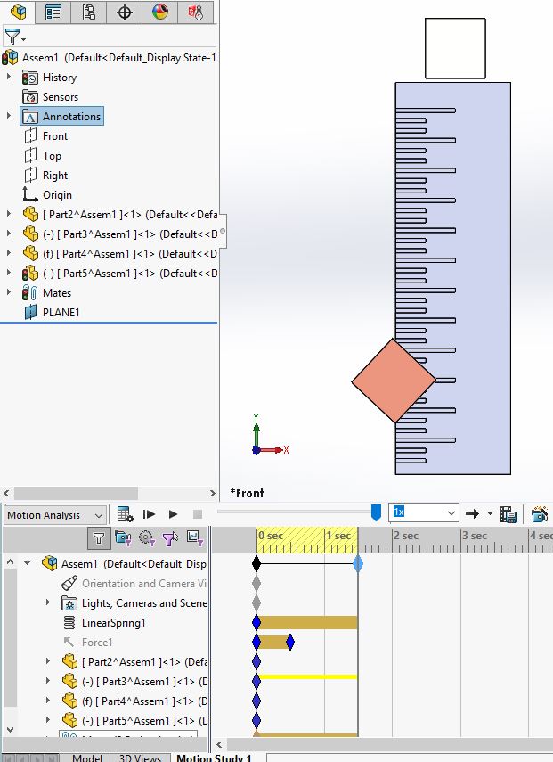
SOLIDWORKS Motion has the ability to capture real world dynamic motion. You just have to understand what limitations there are to certain inputs such as the force, spring, motor, etc. Let’s take the example of the spring connector from the motion manager toolbar.

Here we have a two mass system that is connected by a spring.
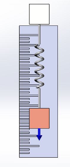
The spring is attached using the faces of each block, however all generated forces are applied at the center of mass of each body. This means that the two blocks are hinged from center of mass to center of mass via the spring. This is completely different than applying a spring connector in SOLIDWORKS Simulation. In that add-on, the nodes on those faces will always stay parallel to each other.
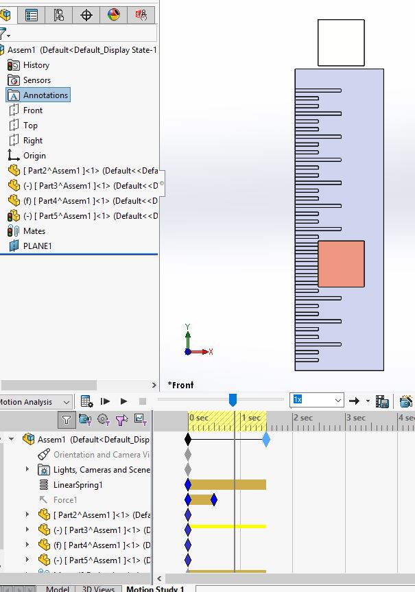
As far as the setup of this system is concerned I have applied a 10 N force from 0 sec to 0.5 sec then turned it off and let the spring force it back. 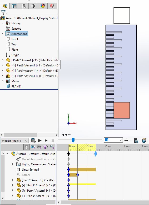
The block stay parallel to each other up to the 1 sec mark.
Then as soon as we pass the 1 sec mark, the instabilities in the calculations (rounding errors) cause the block to start rotating about its center of mass.
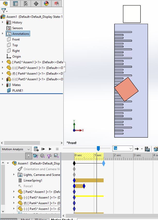
Another limitation of the spring is that there is no lateral stiffness applied. This will cause the system to sway laterally without resistance.
To stabilize the system you will need to add a parallel mate to zero out the rounding errors.
Ketul Patel
Computer Aided Technology