Optimize Your Designs While Cutting Costs with SOLIDWORKS Simulation Tools
 Whether you’re a small or large business owner, an engineer, designer, or laborer there are processes you can adapt to make your job easier. If you have a stake in your business, a reduction in parts could cut your raw material and labor costs and if your company offers a bonus for cost reduction, the reward can be pretty handsome. Even if your company doesn’t have a formal cost reduction program, going into a year-end review with a claim that you saved the company money can help put you ahead.
Regardless if your company calls it “cost reduction” or “Value Analysis & Value Engineering”, it all comes down to making more money on existing products by spending less to make them. It’s the easiest profitability. There are a few tools in the SOLIDWORKS portfolio that are crucial in assisting with this. In this blog, I share how to use SOLIDWORKS Simulation and SOLIDWORKS Plastics to make better products for less cost.
An in-depth understanding of material properties is no longer necessary
My story begins at Michigan State University, where I was a typical engineering student who comprehended a hefty portion of the curriculum and genuinely enjoyed a lot less. The math was interesting but a bit academic because I wanted to be in business before I wanted to be an engineer. Some people fall in love with the math involved in designing a gear train, but I’m more interested in profitability. I need a business case.
During a guest lecture in my Mechanical Design class, I finally got what I needed. The lecturer spoke of the many projects his UK owned engineering firm participated in. The most memorable was an example of a lens cap from an SLR camera which replaced two springs, a retainer clip, a washer, and a screw with a single piece of plastic. The improved design required no tools to assemble, no nimble finger to hold each part in place, and no inspector to verify everything worked. His new one-piece mechanism snapped into place and the assembly process was its own inspection.
 The lecturer nor his company were a part of this design, but he showed a magnificent work of engineering. I still remember his comment that it “took an in-depth understanding of material properties.” Of course, the point of this blog is that it no longer does.
I graduated at an unfortunate time when Michigan’s economy was still suffering and jobs were hard to come by. I worked my way through college working for a Land Surveyor where a large portion of my job was finding and marking property corners of recently sold homes. These types of “surveys” were mostly conducted with an inexpensive tape measure, metal detector, and a can of fluorescent spray paint. We would metal detect until we found the first corner, then measure the distance noted on the plat in the direction of the next property corner, working our way around the lot.
Using SOLIDWORKS Simulation tools to identify, minimize, and correct mistakes
The summer after I graduated my wife and I went to a flea market where a 300’ tape measure caught my eye probably because it seemed unnecessarily complicated. There are eight screws and eight nuts that don’t belong, a couple of metal stampings that required a stamping tool which never even needed to be made. At 2¢ each, the screws and nuts add 32¢ to each assembly, $10/hr labor and a minute to assemble the nuts and screws adds another 17¢. Close to 50¢ on an assembly that can be bought in bulk for $2.00 is a significant cost savings opportunity. But changing a design can be risky and time-consuming, and as previously noted can take “an in-depth understanding of material properties”, or just the right tool.
Making changes to a known money making product can be a lot like killing the goose that laid the golden egg if those changes result in product failures, loss of customer confidence, delivery delays or recalls.
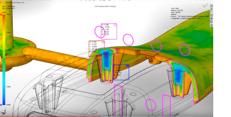
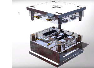
SOLIDWORKS has the tools to identify, minimize, and correct those goose killing mistakes before they happen, and I’ll show you how. Watch my recorded webcast where I’m using SOLIDWORKS 3D CAD to model plastic snap features that will hold the housing together without the added need of cost or labor of screw and nuts. I’ll demonstrate how to verify strength durability of the snap features using SOLIDWORKS Simulation. Once the snap features are properly designed, I’ll explore ways to reduce the cycle time of the injection molding process and save even more money by removing plastic resin from the design where it isn’t necessary with by using SOLIDWORKS Plastics.
I’ll also run a simulated drop test using SOLIDWORKS Simulation to guarantee we haven’t made the mistake of making the parts less durable than they should be.

Related Articles
SOLIDWORKS With Simulation: Is it Enough?
SOLIDWORKS Simulation 2018 and Topology Study
SOLIDWORKS Plastics Simulation – Can Software Replace Human Observation?
About the Author
 Nathan Sneller is a mechanical engineer, entrepreneur, and adjunct professor. Before joining Fisher Unitech, Nathan graduated from Michigan State University, taught Mechanical Design at Grand Rapids Community College and ran an engineering firm where he specialized in the development of electro-mechanical products. In his current role, Nathan advocates for incorporating simulation software into the design process to shorten the development cycle, improve product performance and maximum profitability.