Optimizing Support Material Usage for FDM
The fundamentally different nature of FDM printing grants a vast amount of freedom when it comes to what can be printed. That freedom, however, usually comes at the cost of large amounts of support material usage. Internal cavities, overhangs, nested parts, and functional joints are all possible because of sacrificial support material. Today I would like to share a method with you that allows for complex features but helps conserve support material.
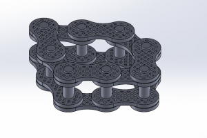
That method is to print multi-part structures fully assembled. To illustrate this, I prepared a small chain assembly in SOLIDWORKS.
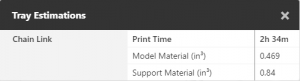
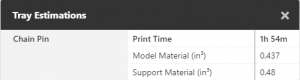
Moving each part file individually into GrabCAD Print, we generate this tray layout and build estimates using basic support setting.
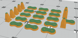
As shown in Orange, there is an excessive amount of support material required. That is especially so with the pins.
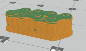
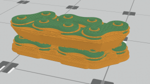
When we transition to the assembled structure, that excessive material is condensed so that the required support for one part is also supporting other parts.
Already we have reduced the required support material by almost 30%. Additionally, there is no longer any need for fastener components.
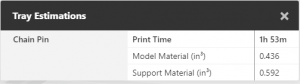
We can take this one step further by using GrabCAD’s SMART support setting. With this support structure, we save more than 40% of the support material when compared to the original tray.
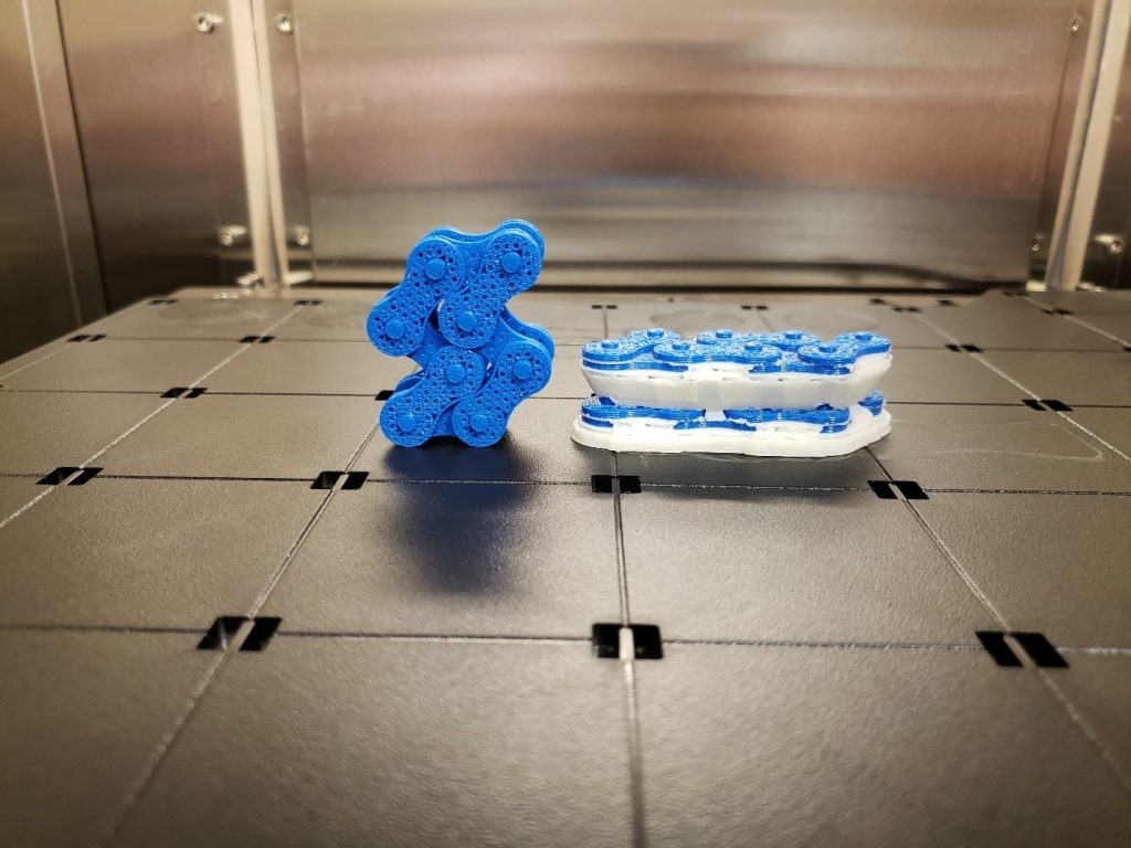
Printing assembled structures can also reduce the overall build time, eliminates the need for construction after the parts have been cleaned, and allows for the design of more complex connections between parts that are impossible otherwise.
To take advantage of this method parts and assemblies should be designed with this process in mind. Determine the slice height and toolpath width you will be building with first. Slice height is chosen by the user under tray settings. GrabCAD does not directly show what toolpath width it is printing with. Through experimentation, one of CATI’s Mark Abshire determined that the settings for the F370 follow the values shown in the table below. If you are printing with Insight, toolpath width can be defined.
| F370 Extrusion Width for GrabCAD Print | ||||
| Slice Height | 0.005″ | 0.007″ | 0.010″ | 0.013″ |
| ABS | 0.014″ | 0.014″ | 0.020″ | 0.026″ |
| ASA | 0.014″ | 0.020″ | 0.020″ | 0.022″ |
| PC-ABS | 0.014″ | 0.014″ | 0.020″ | 0.026″ |
Parts that stack on top of one another, like the links in the chain, should be separated by at least the slice height of the print so that a layer of support material is created. If there is a connection similar to the links and pins, where both parts exist in the same layer and need to move, should be separated by at least one toolpath width. Before you print, inspect the slice previews to verify that support is being generated between parts and adjust your design accordingly.
Hopefully, this technique expands the savings and design freedom you already enjoy with additive manufacturing and we look forward to seeing what you create.
Collin Manchester
Application Engineer, Manufacturing Solutions
Computer Aided Technology, LLC