Reclaim Control of Your Routes
Reclaim Control of Your Routes
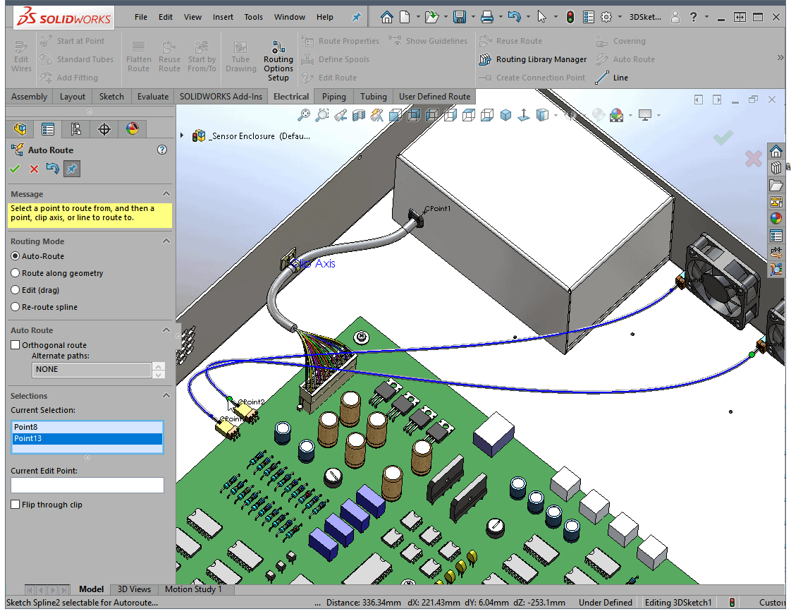
SOLIDWORKS Routing makes it extremely easy to generate complex routes of rigid pipes, flexible tubing or electrical cables in your assemblies. One of the many tools that makes the process so fast is Auto Route. In this simple electronics enclosure all I need to do is select the beginning and end points of the connectors and Auto Route takes care of the rest.
While this technique is fast, it’s not perfect and a just a start to getting the Route positioned exactly where we need it to be. You can see that one route passes through the power supply enclosure and the other passes through a connector. Clearly, my routes need some adjusting.
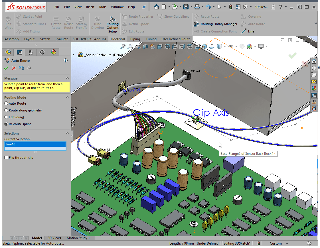
One option is to utilize clips in your Route. Clips are parts that contain the necessary Route Points and an axis, named “Clip Axis,” to control the shape of the route. You place them with Assembly Mates adjust the position by changing dimensions (in a distance mate) or a simple drag. The Routing Component Wizard will walk you though the steps of creating your own.
These clips work great and give you all the control you could need. But, what if your product doesn’t have clips and you just need to easily move the wires? Let’s introduce another way.
One thing to understand about flexible tubes and electrical routes in SOLIDWORKS Routing is they’re splines. Splines are positioned by the number of the control points they contain and, in the examples shown here, they’re two-point splines so they will take the shortest past from beginning to end.
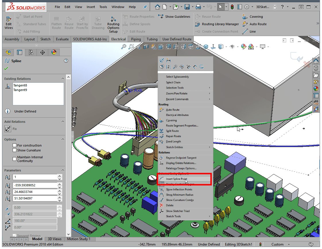
Let’s reclaim control of our routes by adding a few spline control points and using a lesser known command called Show Sketcher Triad. Spline control points are added with a right click and then selecting on the spline where you’d like to place them. Add as many as you feel you need, a few to used move the spline and others to keep the spline from moving.
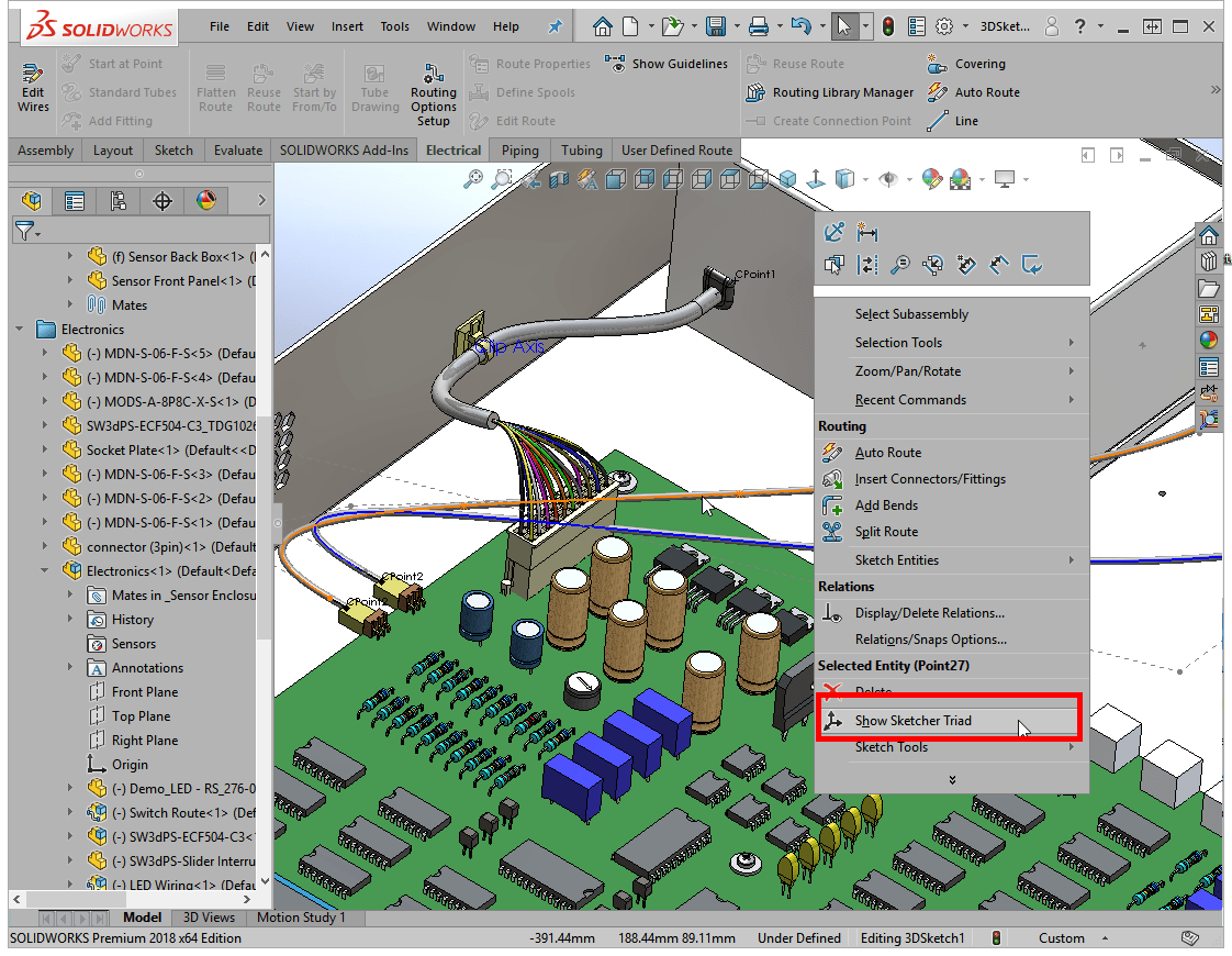
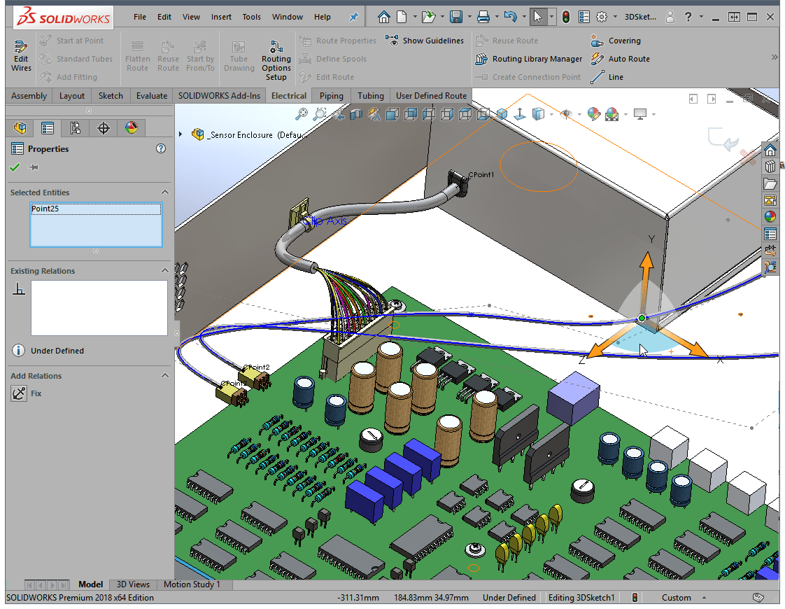
Once satisfied with our spline points, it’s time to break out the Sketcher Triad and move these points where we want them. Right click on a point to move and select “Show Sketcher Triad.” You’ll be presented with a very easy to see and use triad to adjust the points.
With the triad attached to the spline point, you have full control to move the point in only the X, Y or Z directions by clicking the appropriate axis. If you’ve created Section View or an assembly Exploded View, these work in a very similar way. If you need to move a point within the plane, select the “wing” between the axes. Down below I’ve selected the ZX plane and can easily position the point without any Y movement. When finished, right click and select Hide Sketcher Triad to turn it off. Continue using Show Sketcher Triad to place the spline above, below or around any components in your assembly.
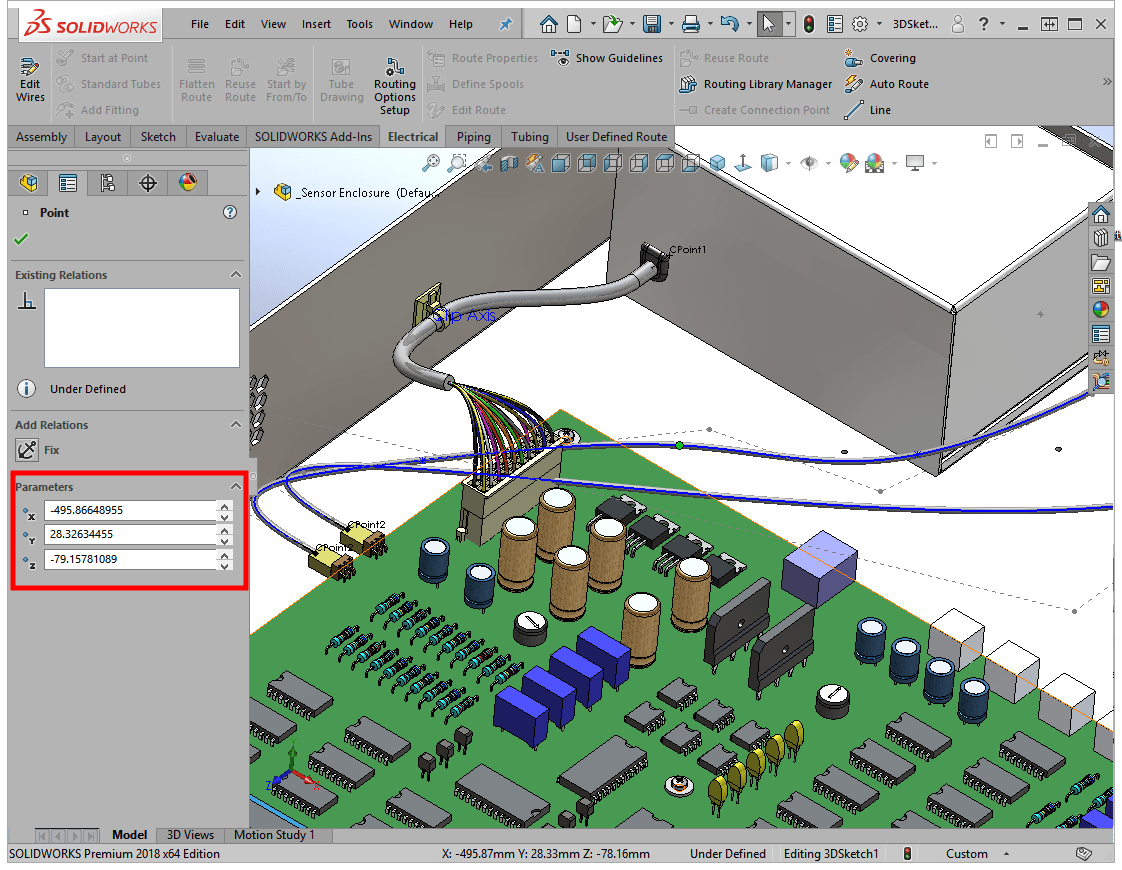
Another quick way to adjust a spline point is to use the Parameters area in the Property Manager. Just remember that these values are from the model origin, so it may be tricky to know if you need positive or negative values. Click the Spin Box arrows to move the point a set increment as defined in Tools, Options, System Options, Spin Box Increments.
Don’t forget that you can also add dimensions to spline points and enter whatever values are needed. The next time you’re working with a flexible tube or electrical route, or any spline for that matter, you now have a few tools to reclaim that control you need.
Kris Dubuque
Field Services Technical Manager
Computer Aided Technology

 Blog
Blog 