Rocket Science is Easy! The Calculations
As mentioned in “Rocket Science is Easy“(the previous blog in this series), a set of fundamental calculations need to be completed before the rocket design can be finalized. The calculations are the basis for the rocket’s stability and performance. The stability calculations will be addressed first, as they have a direct effect on the performance of the rocket.
Stability Calculations
Two variables directly affect the stability of a rocket, The Center of Pressure(Cp) and the Center of Gravity(Cg). The relationship between these two variables determines a stable or unstable design. The rule of thumb for any rocket designer is to keep the Cp below the Cg (given a rocket in the vertical position). Typically a spacing of at least 1 body tube diameter apart is recommended. The more distance the more stable the rocket, and the inverse to this rule also applies.
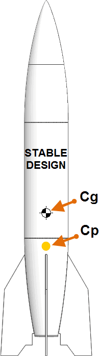
Cg
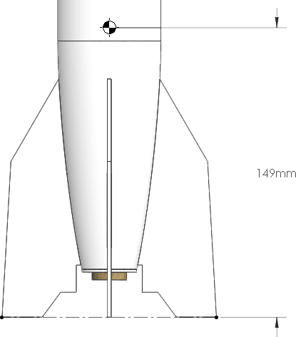
Because the design was generated in SOLIDWORKS the center of gravity is easily acquired. An ABS material was assigned to all the bodies in the part model. The material properties assign density to the bodies allowing SOLIDWORKS to calculate the mass, and the overall center of gravity. Assembly modeling was used to add a C series motor from Estes. The motor was modeled as a single body representing the size, and the mass properties were overridden to be that of the real motor. The recovery system and motor retaining clip is neglected for the Cg calculation as they are negligible. The Cg for the original design is located 149 mm from the bottom datum of the rocket.
Cp
The calculations to properly acquire the Cp of the rocket utilize calculus and the pressure variance of the fluid on the rocket. Fortunately two simplified calculation methods exist for finding the Cp of a rocket. Neither method involves calculus but do require an understanding of the projected area of the rocket’s profile. Use of a the “convert entities” sketch command allowed for an extrusion of the projected area.
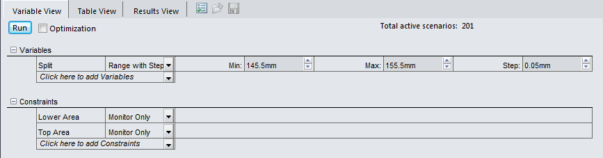
The first method used to calculate the Cp is the “Equal Areas” method, that states the area in front(Af) and behind(Ab) the Cp should be equal. When the areas are equal the Cp is located along the center line of the rocket at the reference dimension above the datum.
Af =Ab
The use of two design studies made finding the Af and the Ab quick and easy. The projected area feature was divided using a split line. A set of sensors were used to report area values as the split line changes in height according to a given range of dimensions. The first design study narrowed the range of the height dimension from 140 mm – 200 mm, to 145.5 mm- 155.5 mm. 201 steps were used in the second design study showing equal area to within less than 0.25% difference.
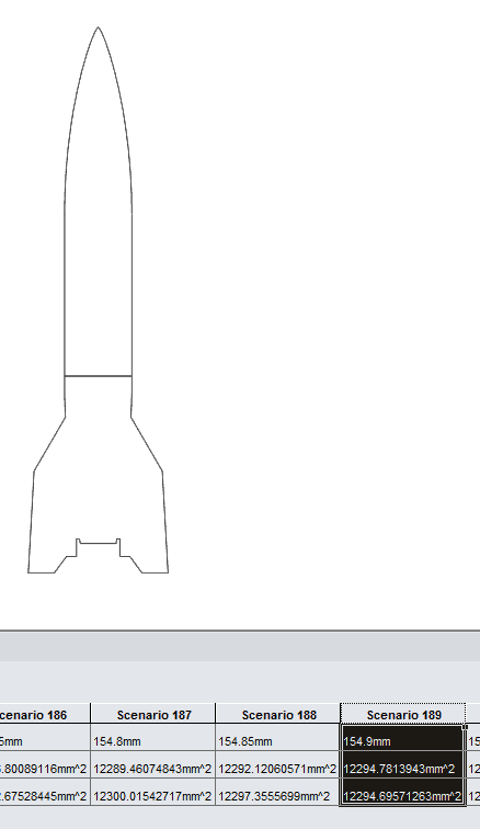
Using the equal areas calculation the Cp distance from the bottom datum is located at 154.9 mm.
“By Parts” is the second method of calculating the Cp. Cp by parts utilizes the location of the center of mass for each part noted by y-bar measured from the bottom datum. The y-bar for each part is then multiplied by the the projected area of each part (Ap). The total area (At) divides the summation of the y-bar and Ap, giving the solution Y-Bar.
Y-bar = (Sum(y-bar*Ap))/At
Note that the area of the fin is multiplied by 2 to account for both stabilizers.
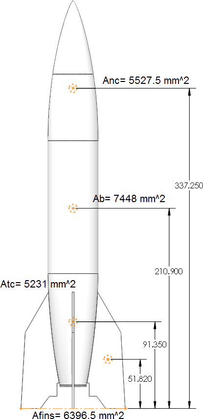
The Cp location for the “By Parts” method calculated to be 172.5 mm from the datum.
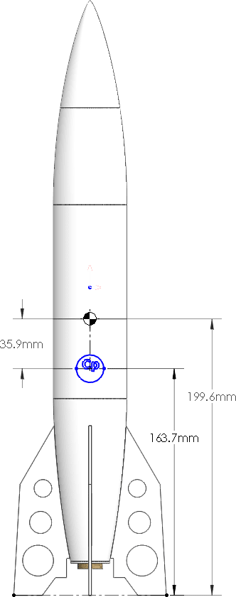
Referencing a college dynamics report I wrote on rocket design the best approximation for the Cp is an average of the two methods discussed above. The average of the two calculations was determined to be ideal based on multiple wind tunnel tests performed for the report.
The Cp for the model V2’s design has an averaged location of 163.7 mm from the datum.
At this point in the design the Cp is higher than the Cg making the rocket unstable. The instability can be rectified two ways. One way would be to shift the Cp. Shifting the Cp down would require a change in area, either by lengthening the rocket body tube or increasing the size of the fins. Because the model V2 needs to remain scale this is not an appropriate change.
The second option would be to shift the Cg. Shifting the Cg’s location can be done by changing the material of the fin, lightening aspects of the model, or adding nose weight to the rocket. The SOLIDWORKS model was changed to include options like Balsa stabilizers, plastic stabilizers with holes, and added nose weight. Because the motor mount uses the stabilizers to fixture it’s position and add structural rigidity, the balsa fins where dismissed. The final design utilizes a combination of nose weight(modeling clay) and lightening holes in the stabilizers. Due to the lightening holes the area of the stabilizer decreases. A thin mylar film known as monokote will be used to cover the holes and restore the projected area. The monokote adds no significant weight to the design and can be ignored for future calculations.
The new Cg is located 199.6 mm, giving a spacing of 35.9 mm. This is not quite the 1 diameter standard separation but the design is stable.
The nose weight added is 37 grams, the rocket is 120.5 grams, and the motor(C6-5) is 24.8 grams, giving a total of 182.3 grams or 0.4 lbs. The rocket is on the heavy side for it’s size, compared to a rocket made from traditional materials. With the overall weight and the motor selected the next step is to calculate the performance specifications of the rocket.
Performance
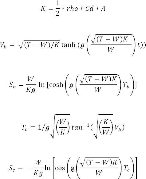
Rocket performance can be described mathematically through the use of derived equations. Three parts of a rocket’s flight path need to be analyzed. The thrust stage(lasts from launch to motor burn out), the velocity and time at burn out, and coast.
- Vb = the velocity at burn out.
- Sb = the position at burn out.
- Tb = the time at burnout.
- Tc = the time of coast.
- Sc = the position of coast.
- W = the weight of the rocket.
- T = the average thrust of the motor.
- g = gravity.rho represents the density of air.
- A = the projected area from the top view of the rocket.
- Cd = the drag coefficient.
- K = wind resistance factors
A = Projected Area Top
Drag Coefficient
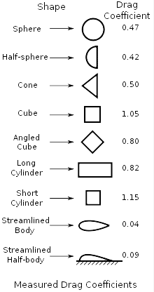
The drag coefficient can be estimated using the type of nose cone the rocket was designed with. For example the table below shows standard Cd’s for given shapes.
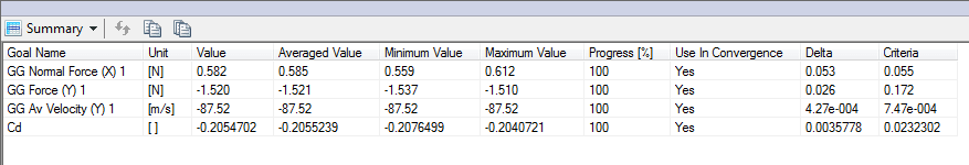
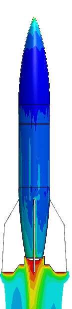
Flow Simulation was used to calculate the Cd for the rocket. The normal force in the Y direction(Fd), and the average Y velocity (v) were calculated during the flow study. An equation goal for Cd was specified as:
Flow calculated the drag coefficient to be 0.205. Note: A conservative value of 0.26 was used for the performance calculations.
Max Altitude
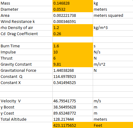
Excel was used to calculate the performance of the rocket from the motor chart values, the calculated drag coefficient, and the weight of the rocket. Sb =38.56 meters, and Sc =89.6 meters for a total altitude of 128.2 meters or 423 feet.
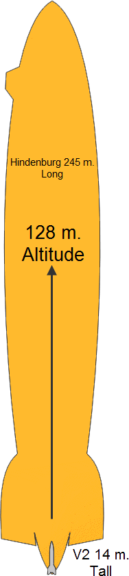
The rocket will reach an altitude of 9 times the height of the original V2, and 1/2 the length of the Hindenburg.
What goes up must come down! Eventually
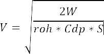
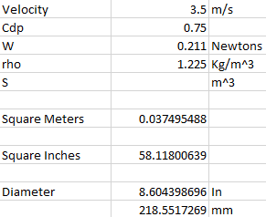
Due to the overall weight of 0.4 lbs, the best solution for the recovery system is a parachute. A reasonable decent rate for a model rocket is between 3.5 to 4.5 m/s. To calculate the size of the parachute the following equation was used, where
- V = the velocity.
- Cdp = the coefficient of drag for a parachute. Usually 0.75.
- W = the weight of the rocket.
- S = the area of the parachute.
- rho = the density of air.
Solving for the area of the parachute gives a diameter of 218 mm or 8.6 inches.
The use of SOLIDWORKS and the calculations above show how easy it is to design a stable and safe model rocket. The rocket design proves to have a good maximum altitude powered by a moderate motor size. The parachute system will allow for a slow and gentle recovery. Please stay tuned for the next blog in the series “Rocket Science is Easy! The Rocket Build“.
Below are reference websites for the theory and equations used in this blog.