Scan to CAD Comparison in VXModel to Double Check Reverse Engineered Models
So you’ve spent some effort to go through the 3D scanning and reverse engineering process in VXModel to get yourself to a fully parametric CAD model. How can you check to make sure your model is accurate to the scan, or the design intent assumptions you made did not throw geometry too far out of spec? Here we will be looking at a quick and easy way to get an answer at a glance.
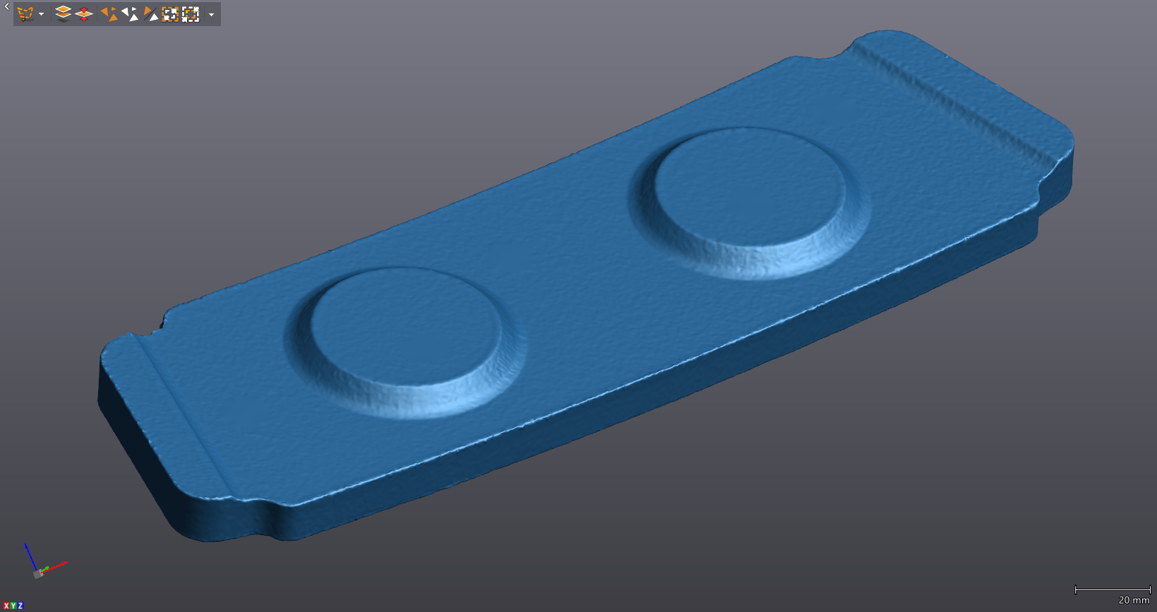
Lets first take a look at our scan. This is one half of a hydroforming tool we would like a CAD file for. First step, as always, is to get a nice complete scan of all geometry we are interested in reverse engineering.
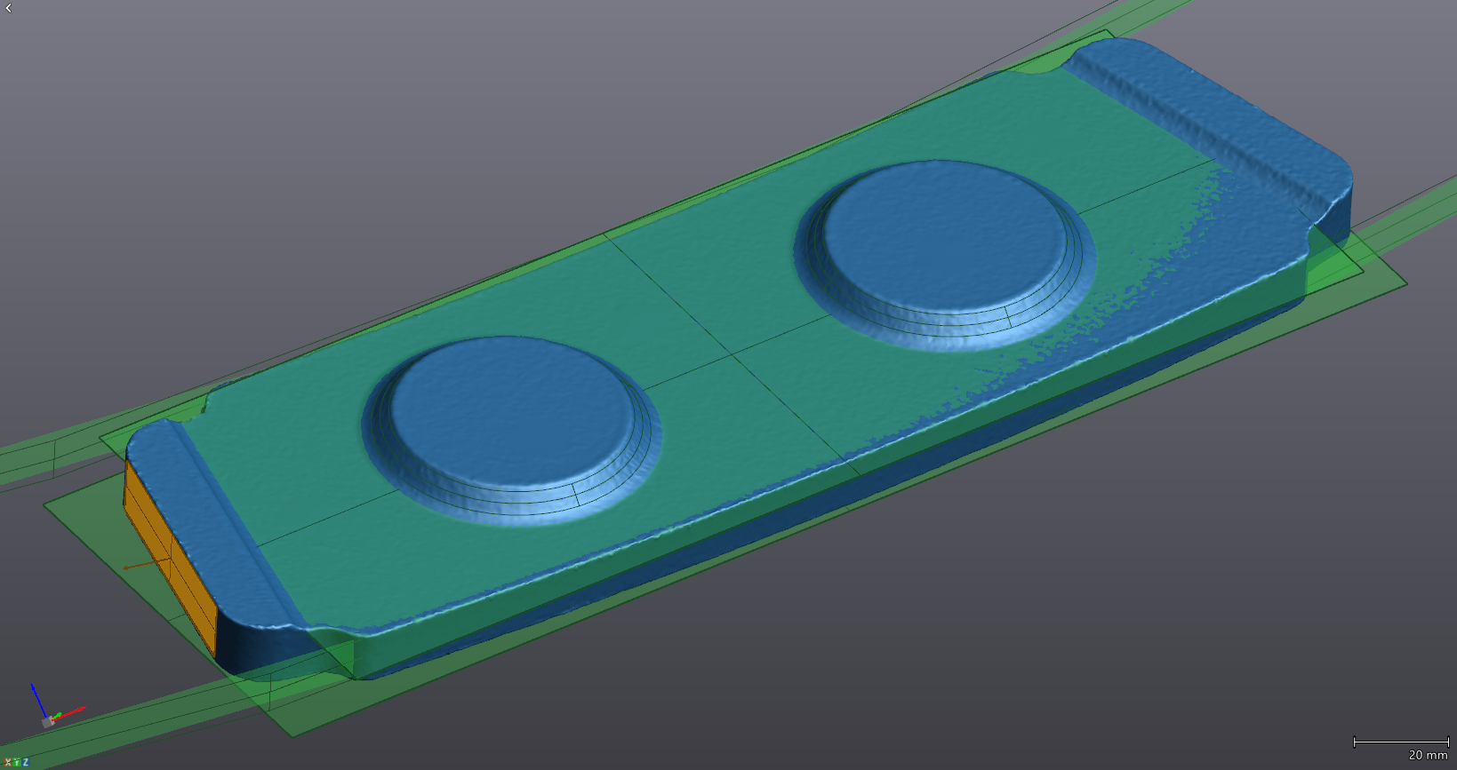
From there, we begin using VXModel to create different geometric entities to be used during our reverse engineering process in Solidworks.
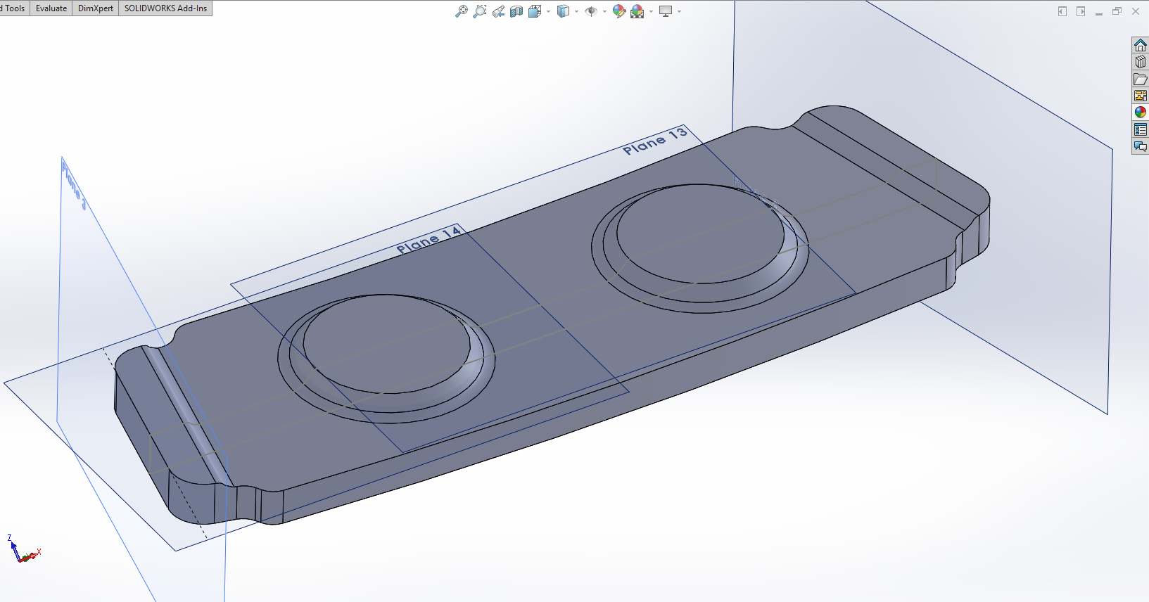
Using those entities as references within SOLIDWORKS, we create our parametric solid model.
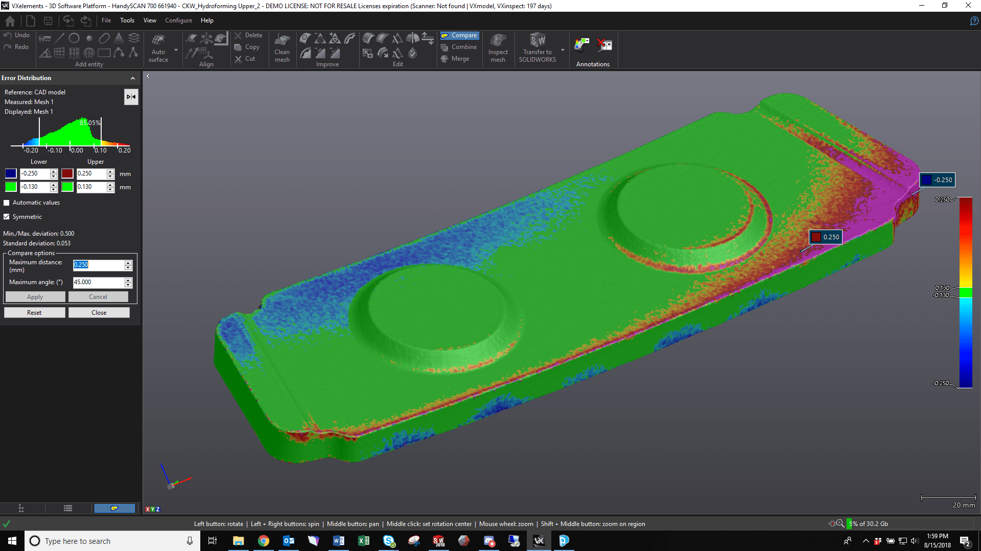
But now the question remains, how good of a job did we do? By importing this file back into VXModel we can easily check using the “Compare to CAD Model” Function.
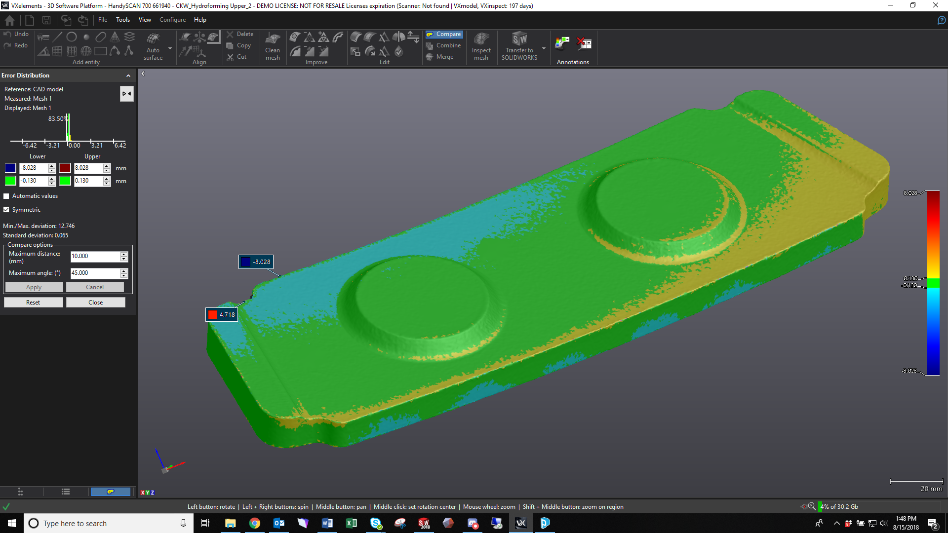
Here we can see a color map and deviation information comparing our CAD model to our original scan. With these default settings we can see our colormap tolerances are too wide, showing max and min points of between 8 and 5 mm. These points are most likely due to small holes in the scan we missed or some other minor errors. This is confirmed by taking a look at the error distribution data in the left. Essentially, we are too zoomed out. An easy fix in the settings menu on the left.
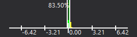
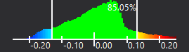
Narrowing our error filter down to 0.25 mm gives us a much better distribution as well as max/min points that are not on a sharp edge (something that is often a cause of disagreement between the scan and CAD data as scans never have truly sharp edges while CAD data has mathematically perfect sharps).
Additionally, we get a much more detailed error distribution. We can now see that 85% of the CAD model is within 0.013mm compared to the scan.
So again, this is just a quick reference to be used to make a gut check on your reverse engineered model. If we want solid data (that we haven’t cherry picked for nice looking data), we would take the comparison even further with a true QC inspection in VXInspect.
Cullen Williams
Rapid Prototyping Application Engineer
Computer Aided Tecnology, LLC