Simple Methods for Editing Imported Solids
As an Application Engineer with Computer Aided Technology, I often work with customers who have received files with intermediate file formats like; IGES, Step, Parasolid, etc., and they want to know how to either modify or re-engineer the solid models or assemblies in SOLIDWORKS.
Here are a few simple steps that can be performed to prepare the model for modification:
- Perform import diagnostics.
- Remove cosmetic fillets.
- Remove unwanted holes.
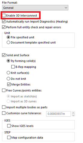
Before opening any of these intermediate file types check in the System Options – Import area. There is a setting there that, if set, will prevent editing.
It is the first option under the “General” file format called “Enable 3D Interconnect”. Make sure this is unchecked.
Any time you import models of an intermediate file type like ( .step, parasolid, .iges, etc.) the first thing to do is select the template to use for the conversion from your list of part templates.
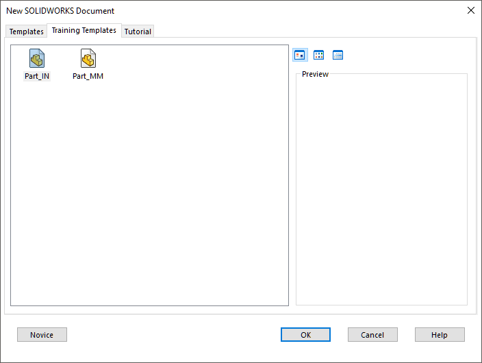
In this case I have selected Part_MM.
Next you will need to perform import diagnostics. Without this there may not be a solid to modify.
You may end up with one or more Faulty Faces, or Gaps.
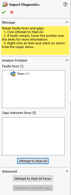
Click on the “Attempt to Heal All” button, then “OK”.
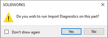
Next you will be prompted to proceed with feature recognition.
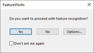
Usually you should just click “no”. This will allow you to proceed step by step through the modifications.
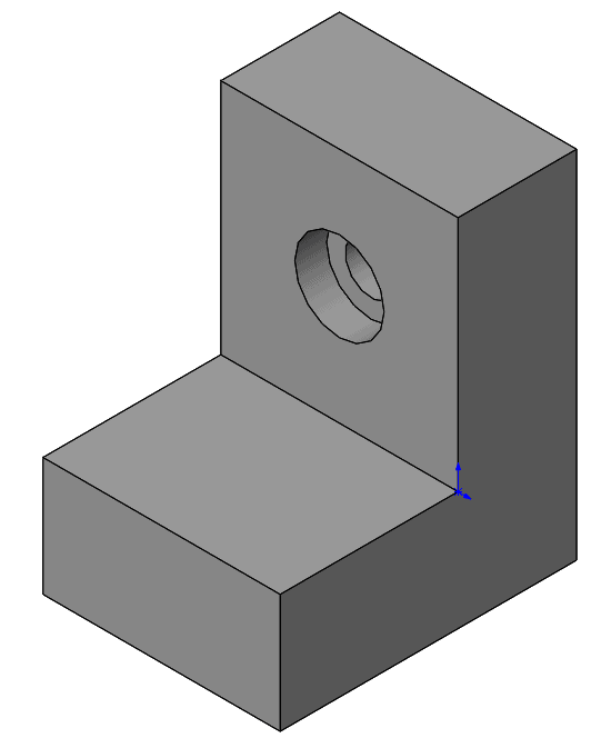
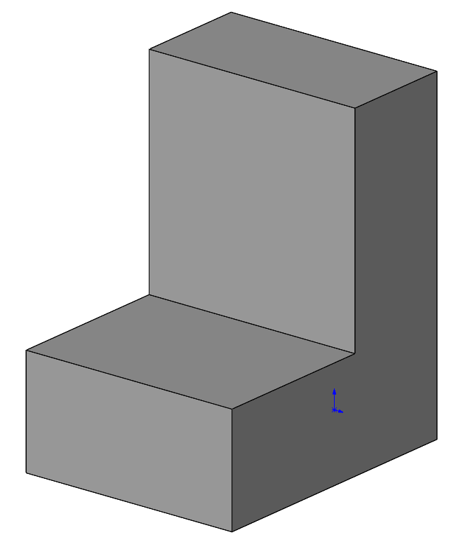
Here is a simple model that I want to modify.
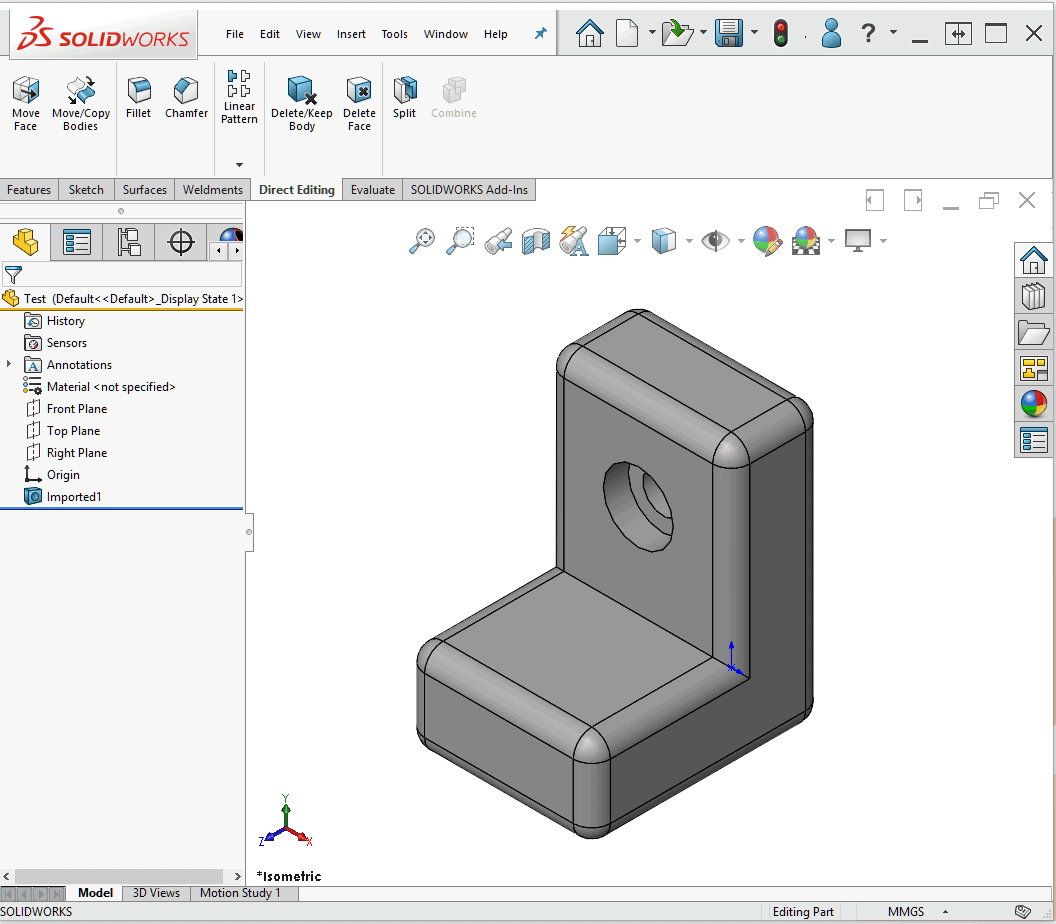
- Make sides equal length
- Reduce Thickness
- Remove Fillets
- Remove Hole
I have indicated above the modifications I want to make.
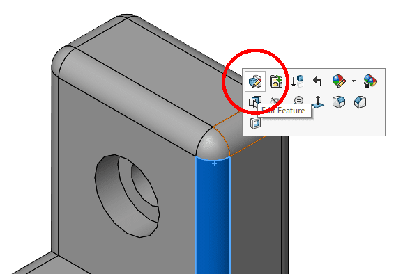
I like to start with the smallest fillets because they are usually the last feature created and perform a cosmetic function only.
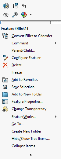
Click on the fillet in the graphics area and select the modify feature button from the popup toolbar.
This will highlight all the connected fillets and add a Fillet feature to the Feature Manager Tree.
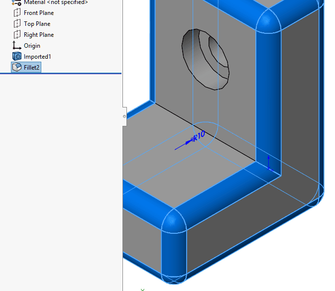
Right Click on the feature and select “Delete”.
This will leave the model looking like this:
Next you will use the “Delete Face” 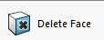 command to remove the Counterbore.
Select all of the inside faces of the counterbore and set the “Delete and Patch option.
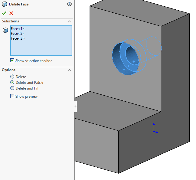
Click “OK” and you will be left with this:
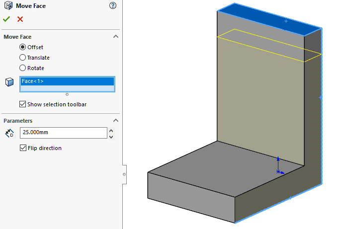
Now you will use the “Move Face”  command to make the other changes.
The Thickness of the part is 50mm and it needs to be 25mm
By selecting the two inside faces and setting the offset to 25mm, this is the preview:
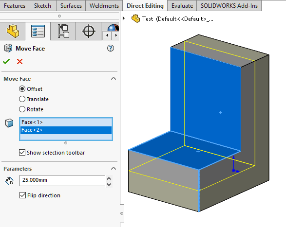
Click “OK”.
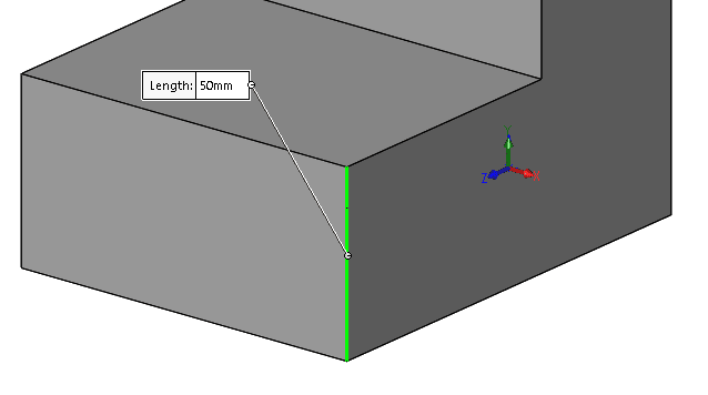
Last if you measure the length of each side you will see that the vertical side is 150mm and the horizontal side is 125mm:
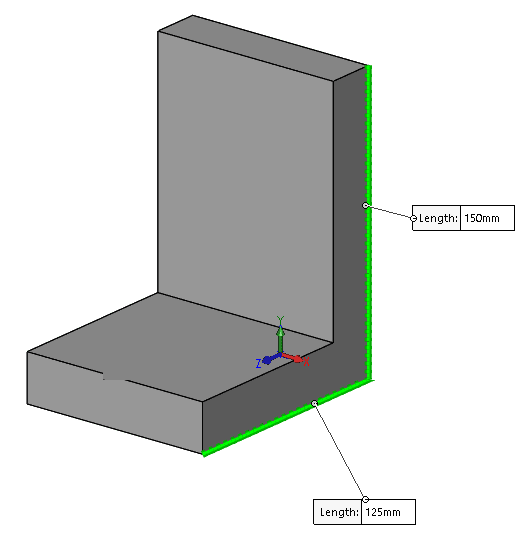
Use the “Move Face” command to offset the long side 25mm, down.
Click “OK”.
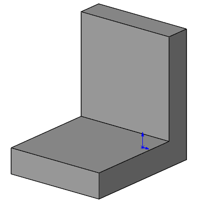
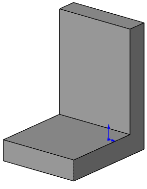
Now you may add any additional features required now that the part is in the correct geometry.
Please try these methods with other intermediate files types.
Dennis Barnes
Applications Engineer, SOLIDWORKS Technical Support
Computer Aided Technology, Inc