SOLIDWOKS Simulation: Nonuniform Force and Pressure Loading in Cylindrical Coordinate Systems
In a previous post “SOLIDWOKS Simulation – Nonuniform Force and Pressure Loading“, I showed how to apply a nonuniform pressure boundary condition to analyze the integrity of the glass walls of an aquarium. We varied the water pressure with depth by referencing a rectangular coordinate system (CS). Let’s look at nonuniform pressure loading using the second option for nonuniformity, a cylindrical CS. We’ll examine the steel horizontal storage tank shown below (approximately 4 ft. diameter by 12 ft. long) exposed to a hurricane-force wind of 90 MPH impacting the tank from the side.
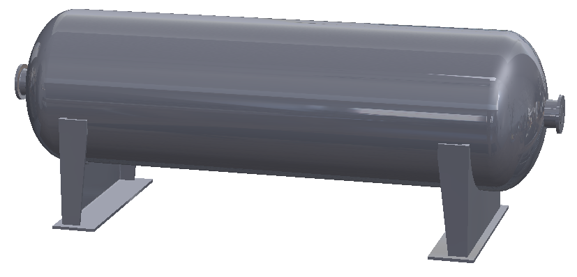
Figure 1: Horizontal Storage Tank
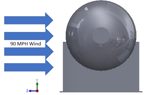
Figure 2: Direction of 90 MPH Wind
Within a SOLIDWORKS Simulation static study, we select alloy steel from the pre-defined material library to apply the properties to the tank and supports. For thin wall components like the tank body, shell meshing is appropriate. Restraints are also added to stabilize the model.
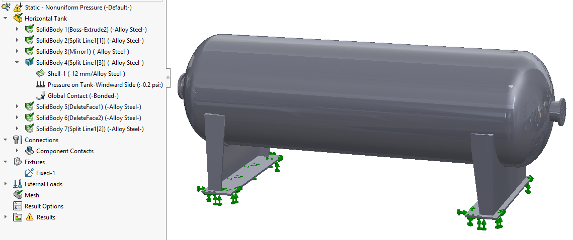
Figure 3: Simulation Static Study Initial Setup
Assume a maximum pressure value of 0.2 psi generated from the wind impacting the tank. Note: this value is the maximum pressure obtained from a calculation performed with SOLIDWORKS Flow Simulation. If you have access to this program, it is possible to simulate the wind environment and export the resulting surface pressures directly to the Simulation tool. Civil Engineering references can also help estimate pressure fields from wind loading.
The pressure varies as the air moves around the tank, so we need to activate the nonuniform pressure distribution. This feature is available within both the force and pressure load property managers. The variation can be applied relative to a cartesian, cylindrical or spherical (CS).
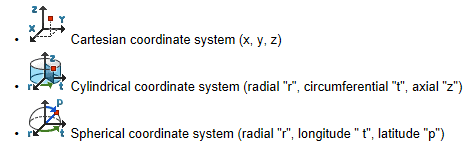
Figure 4: Available Coordinate System Types for Nonuniform Loading
For this wind load, the air pressure is highest at the center of the tank wall where the wind impacts it directly and is forced to go around the cylindrical shape. As it moves around the tank with increasing velocity, the air pressure above and below the tank drops to zero, or possibly slightly below atmospheric pressure depending on the wind velocity. For this analysis, we’ll assume that it goes to zero and use the cylindrical CS option in the pressure boundary condition definition to represent the pressure distribution using a cosine function. To facilitate this relationship in Simulation, a SOLIDWORKS reference CS is first created at the tank center so that the radial, circumferential and axial directions of the tank align with the X, Y and Z axes, respectively. The resulting “Tank Center CS” is shown below.
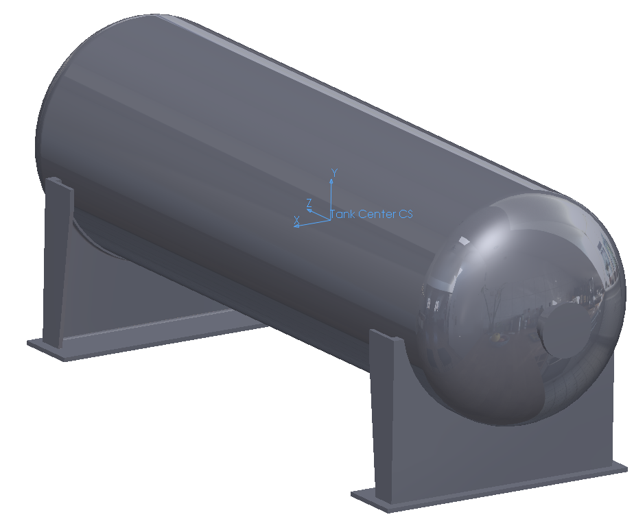
Figure 5: SOLIDWORKS Reference Coordinate System at Center of Tank
We start a pressure load boundary condition, select the “Use reference geometry” option, add the lower tank support edge for the direction and select the outside faces of the tank walls for the pressure application surfaces. Select “psi” as the Pressure Value unit and enter 0.2 psi (the maximum value of the nonuniform pressure that occurs at the middle of the tank) in the Pressure Value field. Check the Nonuniform Distribution box and use the “Tank Center CS” in the reference CS field. Select “radians” as the angular unit, then pick the Edit Equation button and enter the function cos(“t”) for the equation. The “t” designates the tangential (or circumferential) direction.
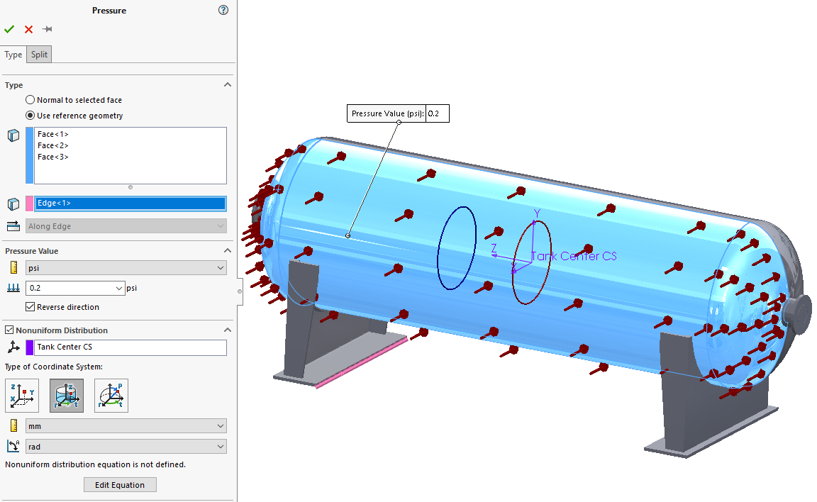
Figure 6: Pressure Load Property Manager (before adding cosine function for pressure distribution)
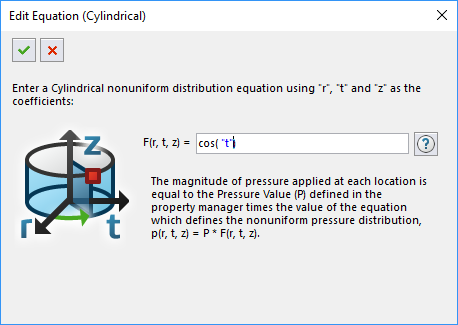
Figure 7: Nonuniform Pressure Equation Editor
The constant value in the Pressure Value field is multiplied by the equation, resulting in the variation of pressure around the tank wall per the cosine function as shown below. The boundary condition icons qualitatively confirm that our setup is correct with maximum pressure applied at the center and decreasing to zero above and below the tank.
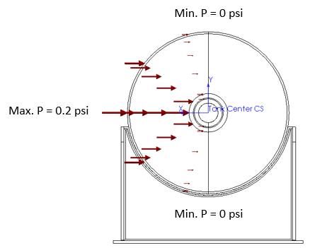
Figure 8: Cosine Function Pressure Variation on the Tank Wall
After solving the analysis, we find that the von Mises equivalent stress is around 300 psi and the maximum deflection of the tank wall is 0.001 inches.
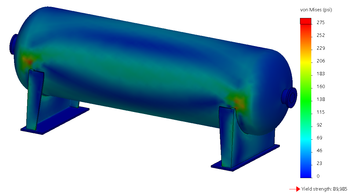
Figure 9: von Mises Equivalent Stress Distribution
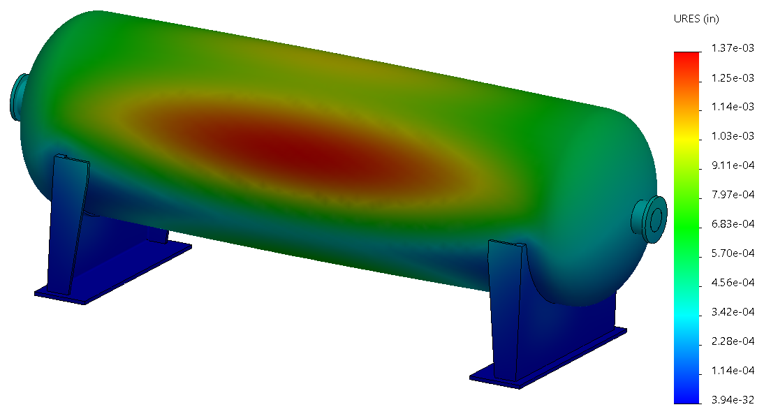
Figure10: Resultant Displacement
This extreme-weather load environment could be combined with other operational loads such as internal pressure, thermal expansion and reactions from attached pipe systems using the Pressure Vessel (PV) study available in Simulation Professional. The PV study can generate worst-case loading conditions and report specific stress values as required by certifying agencies such as the American Society of Mechanical Engineers (ASME) and American Petroleum Institute (API).
I hope this helps increase your understanding of applying nonuniform loading conditions in SOLIDWORKS Simulation. Thanks for taking a look!
Kurt Kurtin
Manager, Simulation and Electrical Products
Computer Aided Technology, Inc