SOLIDWORKS 2016 Curve Driven Component Pattern
Recently I was asked about pattern choices in an assembly model and specifically how using a Curve Driven Pattern vs a Circular Pattern might give the user better results. For instance, the request was to have a way to pattern a set of parts along a circular edge without forcing each instance to always be pointing towards the center of this circular edge.
So I started with an assembly that had three parts mated together some distance from the Origin. Next I created a new assembly level sketch to act as my layout or specifically a construction circle based with the center at the assembly origin:

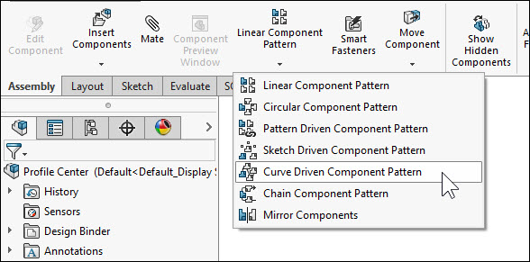
Now I am ready to initiate the Curve Driven Component Pattern command found on the Assembly Toolbar in the Command Manager:
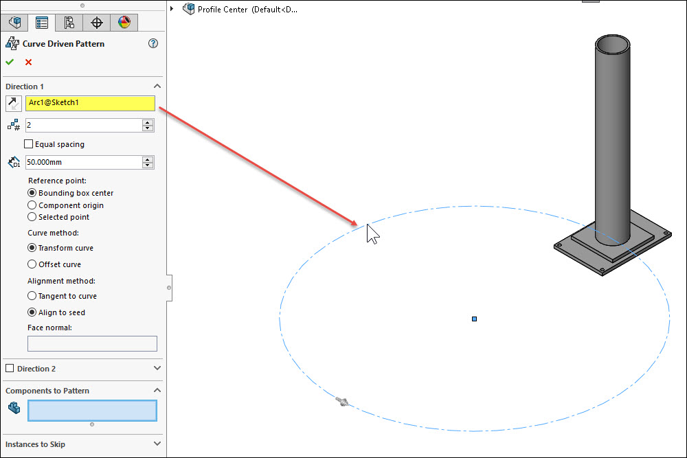
I select the circular sketch from the Graphics Area to define my Direction 1:
Next I select the items that I wish to pattern:
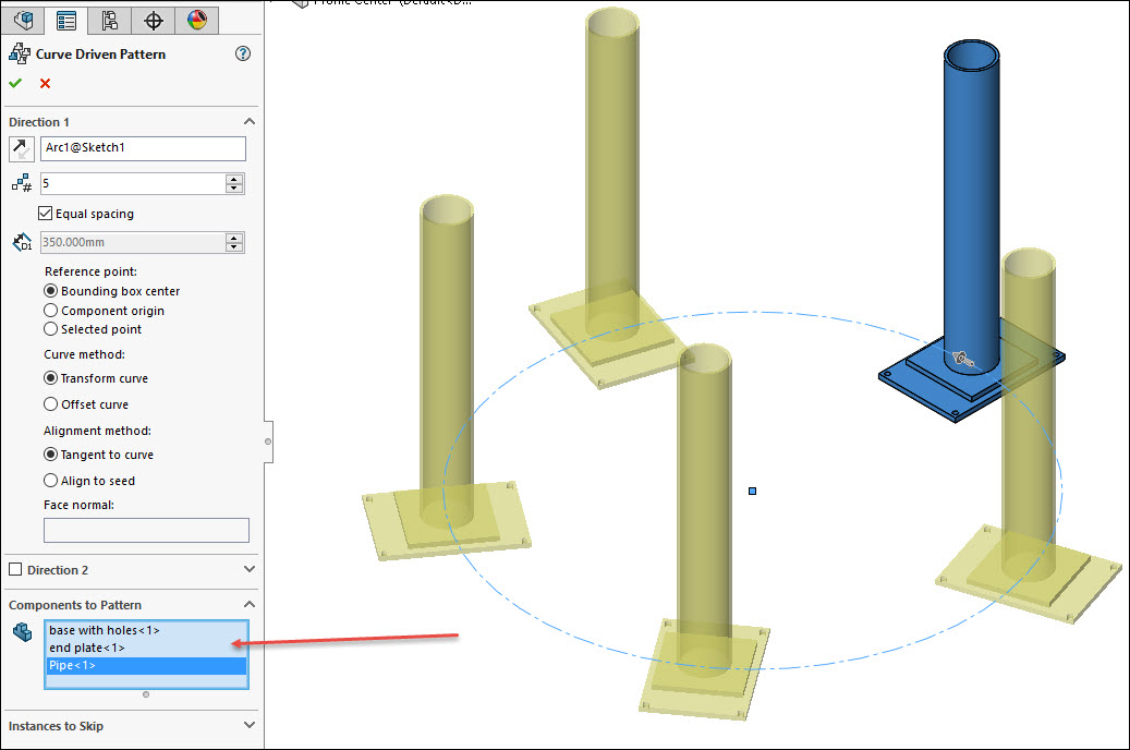
I also set the number of instances that I wish and whether or not to make them equally spaced or a set distance along the circular edge to maintain. Also pay close attention to the setting for Alignment Method. I am showing Tangent at this point:
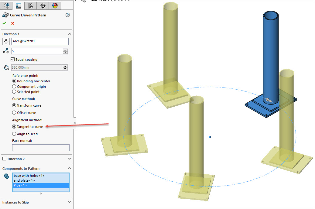
However, if I switch this to Align to Seed, then you see the results below:
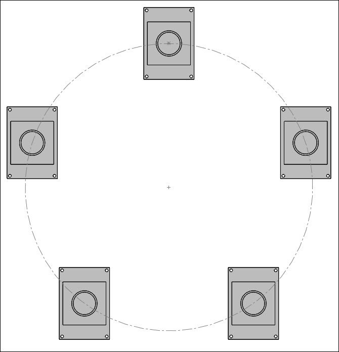
So this is yet another example of using functionality in the assembly pattern environment to yield different results and design choices. Explore more of these options in the Assembly Pattern group of commands.
Thank you,
Brian Reel
CATI Field Technical Services Manager
Computer Aided Technology