SOLIDWORKS 2017 What’s New: SW Plastics Runner Design - Control Valves – #SW2017
SW Plastics Runner Design – Control Valves
Increased realism in SOLIDWORKS Plastics comes with the introduction of control valves in the 2017 release. A technique used in the injection molding industry known as Sequential Valve Gating (SVG) incorporates the use of control valves when multiple gates are used in the injection process. The advantages of SVG are numerous, especially for larger and more complex parts, including greater control of weld line locations, minimization of the adverse effects of over-packing, and reduction of the required clamp tonnage, to name a few.
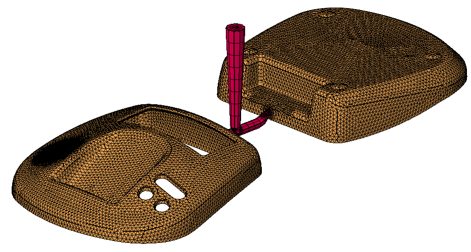
Control valve setup is shown in the following example. In this “family mold” injection simulation, the part and hot runner system are meshed.
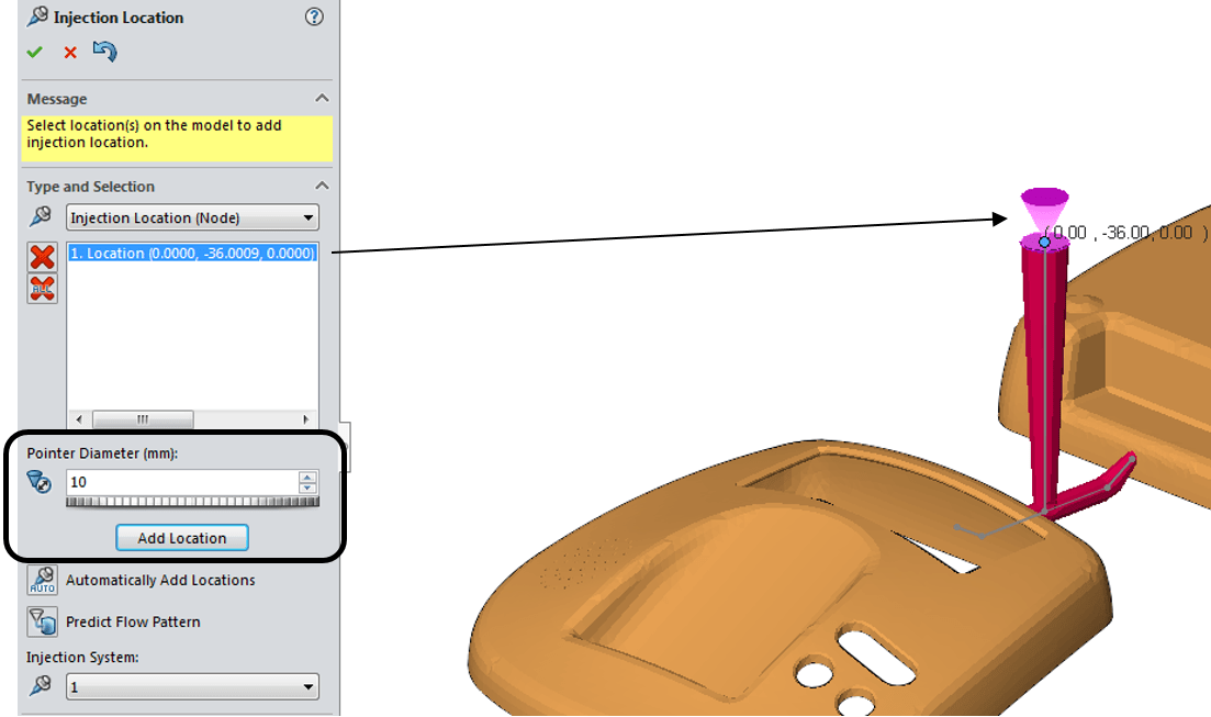
Then, as with previous releases, an injection location is added to the top of the sprue and sized to 10mm.
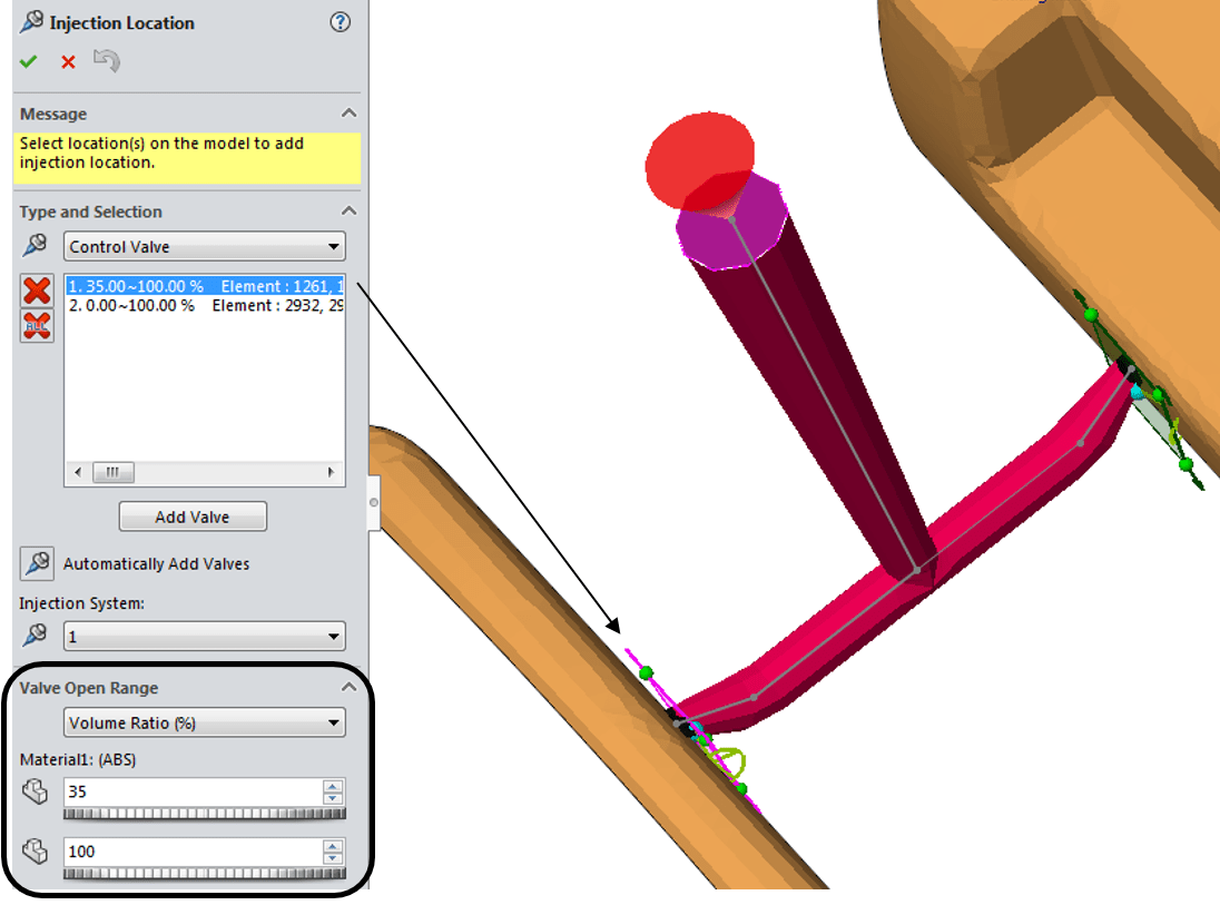
While in the Injection Location Property Manager, we switch to the new “Control Valve” settings and add the locations manually, or let SOLIDWORKS Plastics automatically find them based on where the runner system meets the molded part.
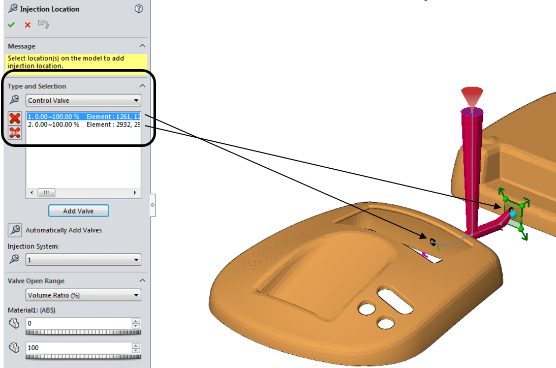
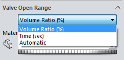
With the desired valve location highlighted, we can instruct the program to open the valve based on one of two manual controls, Volume Ratio (%) or Time (sec), or use an automatic mode in which the control valve opens when the melt front passes the gate.
For this simulation, we want to open the valve at 35% of volume ratio and keep it open for the duration of the filling cycle.
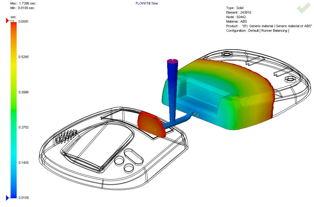
After solving the injection simulation and loading the results, the Fill Time plot shows the delayed opening of the control valve at about 0.6 sec. and the corresponding drop in inlet pressure of approximately 20 MPa.

So, if you simulate the injection molding process for your plastic parts and need to incorporate SVG to get a more realistic simulation, this new functionality in SOLIDWORKS Plastics 2017 is sure to help!
I hope this part of the What’s New series gives you a better understanding of the new features and functions of SOLIDWORKS 2017. Please check back to the CATI Blog as the CATI and MCAD Support Teams will continue to break down many of the new items in SOLIDWORKS 2017. All of these articles will be stored in the category of “SOLIDWORKS What’s New.” You can also learn more about SOLIDWORKS 2017 by clicking on the image below to register for one of CATI’s or CATI’s Design Summits.
Kurt Kurtin
CATI Technical Manager – Simulation
Computer Aided Technology