SOLIDWORKS 2018 What’s New – Shrinkage Percentage in Warp Measure – #SW2018
SOLIDWORKS 2018 What’s New – Shrinkage Percentage in Warp Measure – #SW2018
SOLIDWORKS Plastics 2018 introduces several new features to help us improve the quality of our plastic injection molding analysis and results evaluation. One of these new features, Shrinkage Percentage in Warp Measure, is a modification to the measure tool when reviewing warp results. Let’s look at where this modification is located within SOLIDWORKS Plastics.
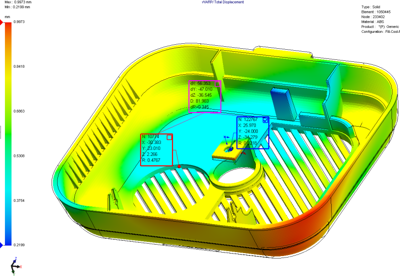
For instance, begin by viewing a warp result for the Total Stress Displacement. Then use the measure tool to select a node for the first location (red box) and a node for the second location (blue box) that you want to compare. In SOLIDWORKS Plastics the purple box indicates the difference between the two selected nodes. The dX, dY, dZ, and D information are the measurement distances along the X, Y, and Z direction as well as the straight-line distance between the selected nodes. For this specific plot, the dR value is the measured difference in Total Stress Displacement between the selected nodes.
If you review the same plot in SOLIDWORKS Plastics 2018, using the measure tool now includes an additional callout in the purple box, dR%, which indicates a percentage value of the shrinkage percentage.
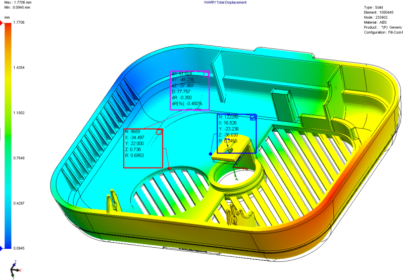
I know what the obvious question is – “what does this shrink percentage mean”? I’ll be quite honest in that I’m still trying to figure out how the dR% value is calculated within SOLIDWORKS Plastics 2018. In my early testing I’ve measured the shrink values on the extreme node locations of minimum shrink and maximum shrink for a test model. The dR% value indicated 1.103%, which I found quite puzzling. I’m sure the details of what this shrink percentage will become clear as the technical documentation for the new SOLIDWORKS Plastics 2018 features are improved. Be sure to try all the new features and functionality of SOLIDWORKS Plastics 2018. Now go make your designs better with SOLIDWORKS Simulation!
I hope this part of the What’s New series gives you a better understanding of the new features and functions of SOLIDWORKS 2018. Please check back to the CATI Blog as the CATI Application Engineers will continue to break down many of the new items in SOLIDWORKS 2018. All of these articles will be stored in the category of “SOLIDWORKS What’s New.” You can also learn more about SOLIDWORKS 2018 by clicking on the image below to register for one of CATI’s Design Innovation Summits.
Bill Reuss
Product Specialist, Simulation