SOLIDWORKS 2022 What’s New – SOLIDWORKS SIMULATION - Blended Curvature-Based Mesher
SOLIDWORKS Simulation 2022, like we have seen in several prior releases, includes updates to the meshing algorithms. Let’s face it. When it comes to finite element analysis, “it’s all about the mesh”, as one of my co-workers often chides. Digging in to new features of SOLIDWORKS Simulation 2022, using the Blended Curvature-Based meshing algorithm, we can now apply a mesh control that has a larger element size than the global mesh settings. This is an interesting change and, in my opinion, a welcome addition to SOLIDWORKS Simulation.
I began investigating this new feature using SOLIDWORKS Simulation 2021 on an assembly with two cast parts, a gasket, and seven fasteners (Figure 1). For my analysis, I am interested in the performance of the top casting and the fasteners. Depending upon the analysis and study type, I might also investigate performance of the rubber gasket to ensure the seal is maintained. The base, highlighted in blue, may be necessary to include in the analysis, however, this bulky component is of lesser importance.
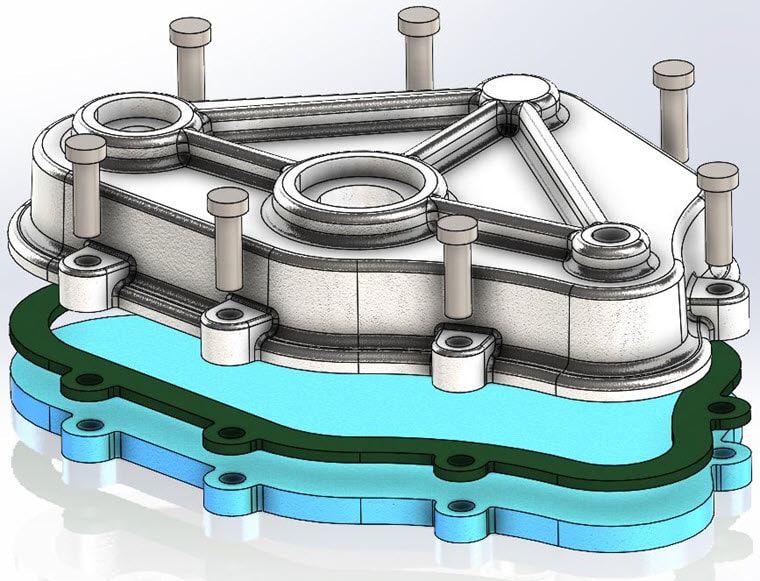
Figure 1.
I created a Linear Static analysis of the assembly using SOLIDWORKS Simulation. I applied a mesh control to the 15 mm thick base specifying a 50 mm maximum and 25 mm minimum element size (Figure 2). No other mesh controls are applied to components in this assembly.
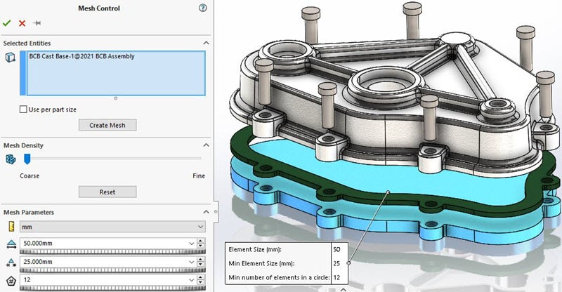
Figure 2.
I then created a mesh using the Blended Curvature-Based meshing algorithm with a maximum element size of 15 mm, a minimum element size of 3 mm, a minimum 12 elements in a circle, and an element size growth ratio of 1.4 (Figure 3).
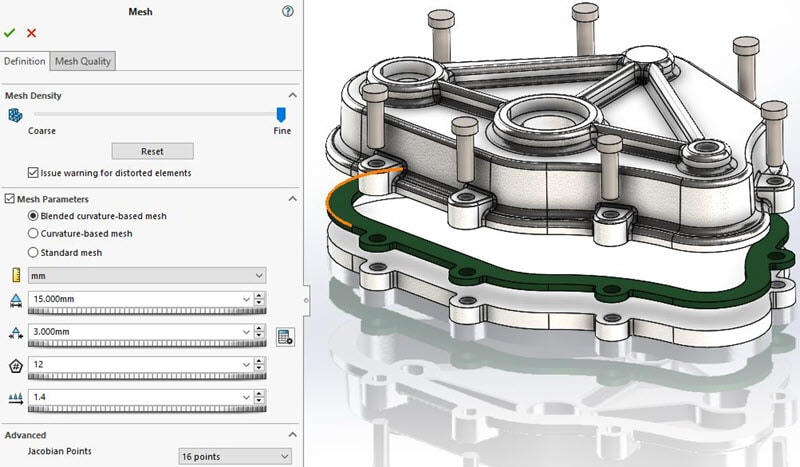
Figure 3.
Once the meshing process completes, a plot of the mesh is generated (Figure 4). At first glance, it appears the coarse mesh control worked as intended. Unfortunately, with some investigation I can verify that the mesh control with a larger element size was not applied to the base component in SOLIDWORKS Simulation 2021.
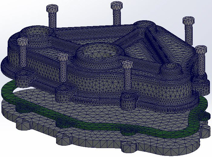
Figure 4.
By right mouse clicking on the Mesh Quality plot, then choosing Probe and List Selected, I can investigate details of the mesh, such as node locations. Specifically, I want to verify the positions and distance between nodes on the base component . For the nodes I selected, the straight-line distance is 15 mm. This is equivalent to the maximum element size specified for the Blended Curvature-Based mesh for the assembly (Figure 5).
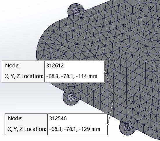
Figure 5.
With SOLIDWORKS Simulation 2021 and earlier, to accomplish the desired mesh sizes – larger elements on the base component, smaller elements on the remainder of the assembly components – I would have to modify my approach . A single mesh control using the 15 mm maximum, 3 mm minimum element size would have to be applied to all components except the base. Then the global mesh setting would be set to 50 mm maximum, 25 mm minimum element size.
Now with SOLIDWORKS Simulation 2022, I can utilize the initial approach I used for controlling the mesh size of the base component. The mesh control applied to the base can create a coarser mesh for this body that may not be critical to the analysis. Using the same mesh control size on the base and global mesh settings on the assembly, the mesh is now created with my desired element sizes (Figure 6). Visually, there is a distinct difference in the mesh created for the base in SOLIDWORKS Simulation 2022.
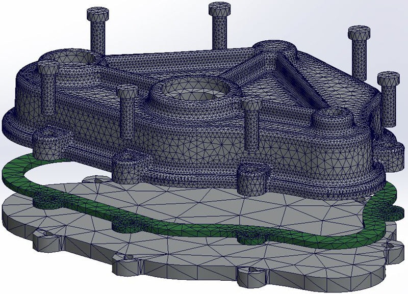
Figure 6.
Again, I right mouse-click on the Mesh Quality plot, choose Probe and List Selected, then change the Property Manager settings to probe Nodes. Selecting two nodes on the bottom face of the base component, I am presented with the cartesian space location of the nodes. With a quick hand calculation, I can verify that the straight-line distance between the selected nodes is approximately 61.1 mm (Figure 7).
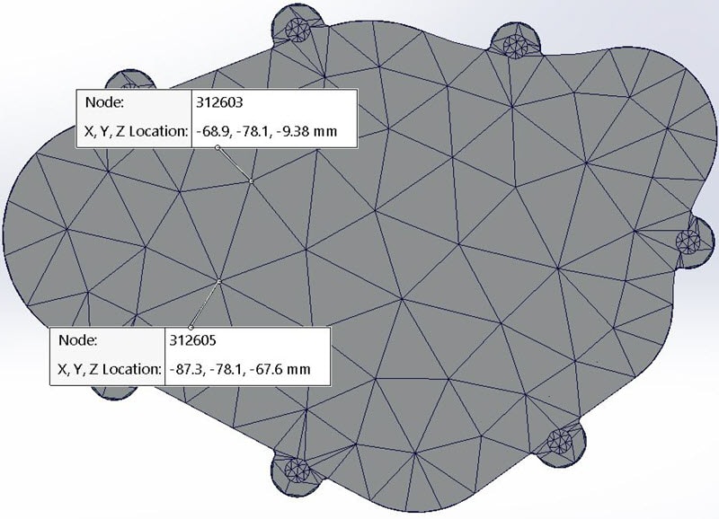
Figure 7.
For the Pythagorean Theorem challenged, I can measure the distance directly using the Probe tool, selecting the Distance option in the Property Manager (Figure 8).
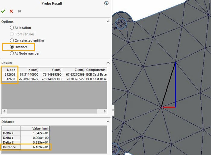
Figure 8.
Now you might question why this distance is not 50 mm, per the mesh control maximum element size. This has to do with the Element Size Growth Ratio setting of 1.4 (Figure 3). This mesh control setting is attempting to blend the element sizes uniformly from one element to the next. By allowing the edge length of elements to be slightly larger than the specified mesh control, the overall size of the mesh, meaning the number of nodes and elements, will be reduced.
Another interesting addition is Mesh Summary, which you can access by right mouse-clicking on the Mesh icon in the SOLIDWORKS Simulation Feature Tree (Figure 9). This adds to the already powerful Mesh Details by including information about the mesh size and controls applied to each component in the finite element model.
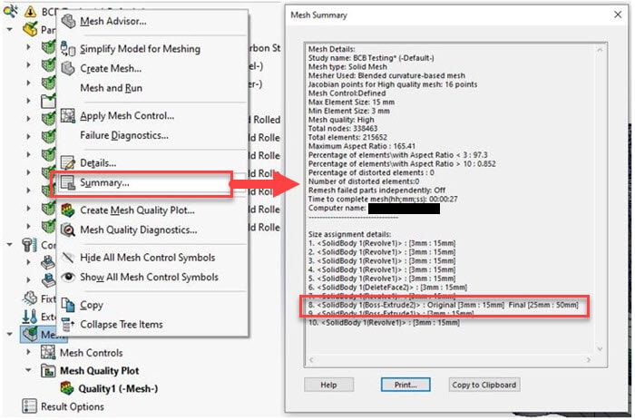
Figure 9.I encourage you to investigate the mesh details and control settings on your own SOLIDWORKS models and learn how to control your mesh with this new option for Blended Curvature-based meshing. Now go make your products better with SOLIDWORKS Simulation!
I hope this part of the What’s New series gives you a better understanding of the new features and functions of SOLIDWORKS 2022. Please check back to the CATI Blog as the CATI Application Engineers will continue to break down many of the new items in SOLIDWORKS 2022. All these articles will be stored in the category of “SOLIDWORKS What’s New.”
Bill Reuss
Product Specialist, Simulation
Father, Golf Junkie, coffee Connoisseur, Computer Nerd
Computer Aided Technology
What is Design Innovation Month?
DESIGN INNOVATION MONTH 2021 – Live Events, Webinars, Virtual Showroom, Contests
Design Innovation Month is CATI’s massive “What’s New in 2022” event for SOLIDWORKS, 3DEXPERIENCE, and 3D printing & 3D scanning technology. That’s six weeks of in-person events, live and on-demand webinars, demonstrations, in-depth blog posts, and prizes! Best of all, it’s free of charge! Check the DI Month Hub for all the details and to sign up for your nearest live event.