SOLIDWORKS: Analyzing Kinematics With 2D Sketch Layout Tools
When we think of SOLIDWORKS, we think of powerful 3D CAD design software. For this post, let’s talk about some powerful 2D functionality that also exists in SOLIDWORKS. We are going explore the Layout sketch tools found in our assembly environment.
Have a multiple bar linkage mechanism that you need to design? The completed design might require bearings, fasteners, rod-ends, and carefully designed bracketry. 3D Modeling all these components to analyze the linkage kinematics will take a significant amount time. However, if your mechanism motion can be represented two dimensionally, then we can save time using the Layout tools in SOLIDWORKS assemblies. This will enable us to work out the rough geometry of the linkage before getting into the more strenuous solid modeling of the actual components.
To take advantage of this approach, we need to simplify components into 2D representations of them. We want to use simple sketches for models of the link components, but we can ignore bearings, bolts, and mounting brackets. In an assembly Layout sketch, we will define these simplified component representations as Blocks. Multiple components can be represented in a single block if we do not desire to examine the motion between those parts. We use sketch relations to function as mates between the various sketch blocks. This allows us to analyze the motion of the 2D blocks that are mated to each other in this single Layout sketch.
Let’s look at how this can be done. For this example, we are looking at the rear suspension layout of a mountain bike. We are focusing on shock mount location and shock specifications to give us our desired wheel travel. Our design goal is to have 160mm or rear wheel travel for this mountain bike.
While all the blocks can be created in a single sketch environment, I prefer to create and save them individually. This makes it easy to develop a “block library” for future design projects.
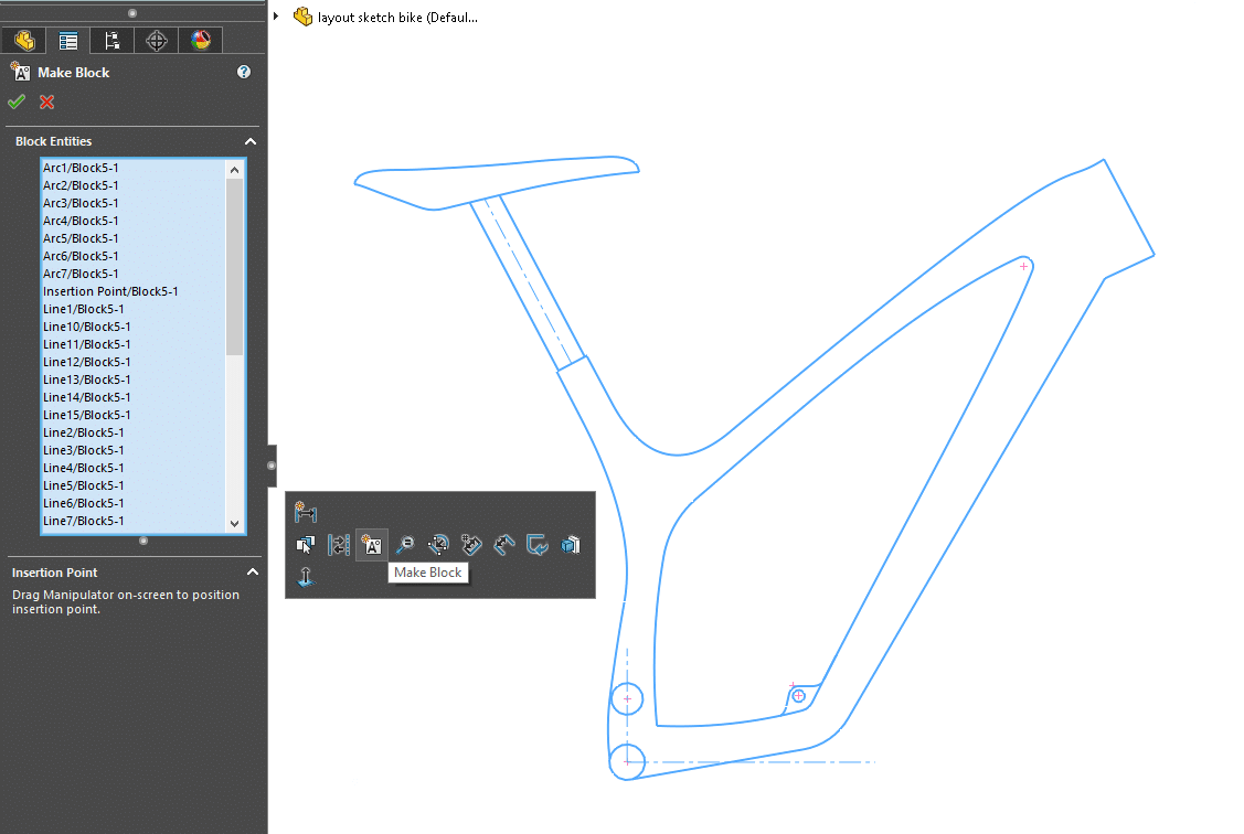
First, we create our simplified sketch and then select “MAKE BLOCK”. This single block represents the bike’s main frame, saddle, and seat post. You can also see that suspension pivot locations and the shock mount locations are represented with circles.
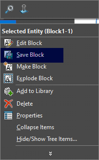
Next, right click on the block from the Feature Manager and “SAVE BLOCK”. I usually save them to the SOLIDWORKS design library.
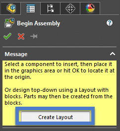
Once this has been done for all of the required components, we are ready to put our blocks together in a Layout sketch. We start a new assembly file and immediately click on “CREATE LAYOUT”.
Once in this Layout sketch mode, you will notice the sketch grid and the “Popsicle-Stick” icon that SOLIDWORKS uses for Layout. You can also see the design library has my recently created blocks for this project.
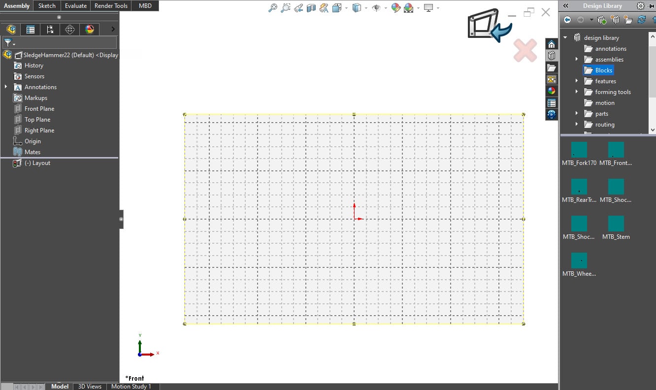
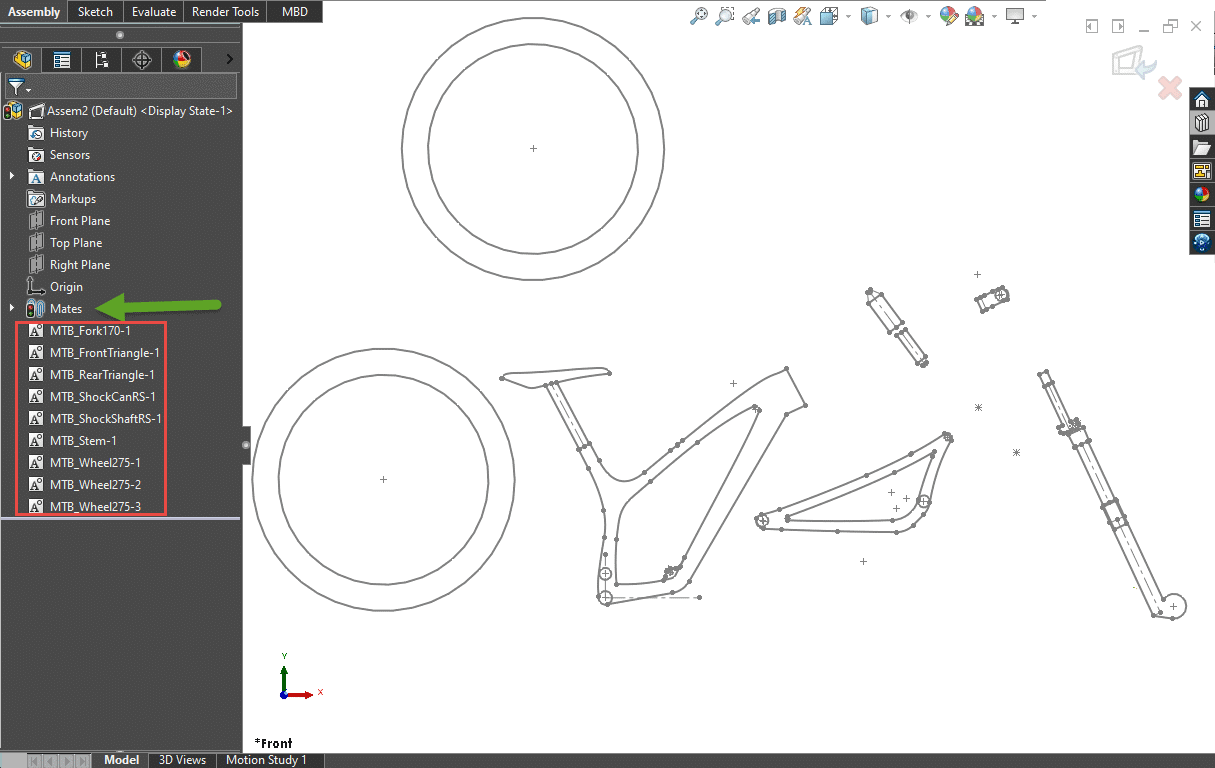
Next, drag in the required blocks. This is very similar to bringing parts into an assembly file. There are no external file references to these blocks. They exist in the design library but are also embedded in this assembly sketch. The feature manager will show the blocks and any relations between them will appear in the “mates folder.”
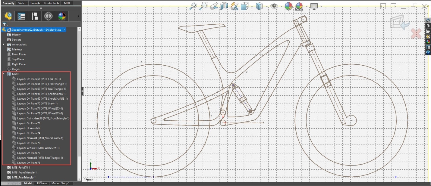
Then, we assemble the blocks. This is easily done by using the CTRL key and selecting the sketch geometry to create sketch relations. These sketch relations will function as mates between the sketch blocks. They will reduce the degrees of freedom allowing us to simulate the real design. While we are editing this Layout sketch, the block’s location and position can be manipulated by dragging them on the screen. These block positions are not constrained by their internal sketch relations. In other words, a HORIZONTAL relation to a segment inside the sketch block will not prevent that block from pivoting. You will notice the sketch relations created between these Blocks will appear under the “mate folder” in the Feature Manager.
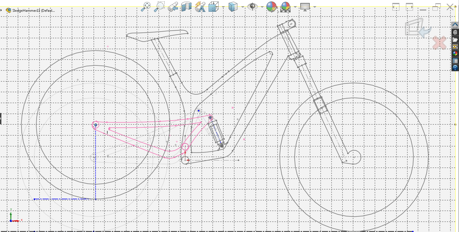
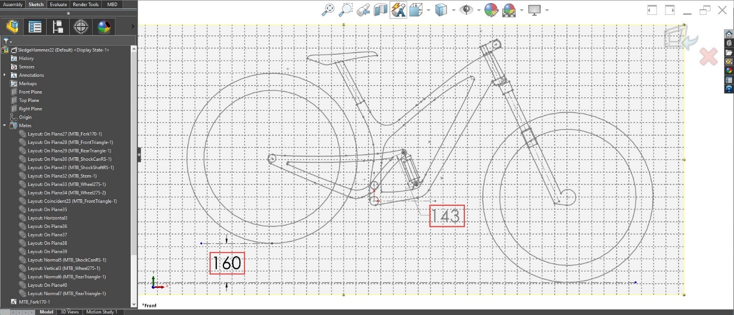
Here, we can drag the rear wheel up and down to see the motion of our suspension.
Using sketch dimensions inside this layout sketch gives us more precise control of the position. This allows us to examine the relationship between wheel travel and shock travel of the mountain bike design. Using a shock length of 200mm gives us a good starting point.
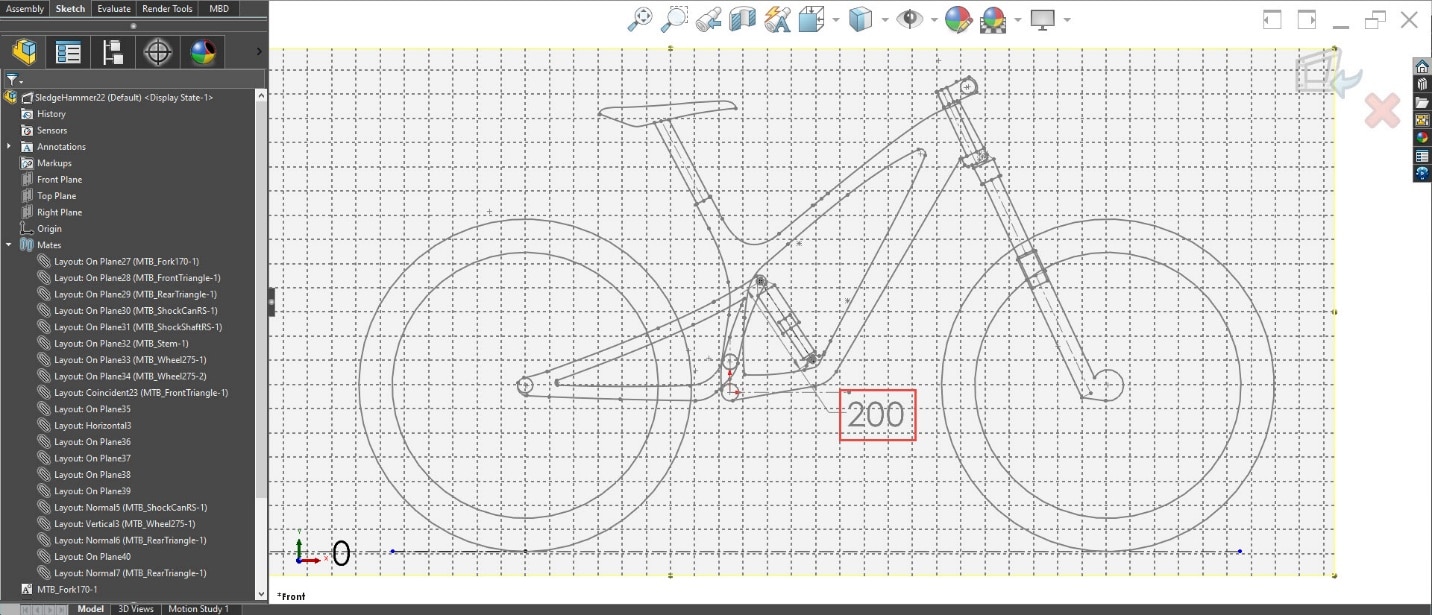
After slight adjustments to the location of the shock mounts, we end up with our goal of 160mm rear wheel travel. This is achieved with 57mm of shock travel with an extended length of 200mm.
For this example, we picked a simple design scenario and focused on shock selection based on suspension travel goals. This same Layout could be used to further analyze more complex parameters of this suspension design. It is much easier to adjust these blocks compared to actual 3D modeled components. Once satisfied with the mounting and pivot locations we would take this geometry information and use it to design the parts in their own SOLIDWORKS part files. If desired, the same sketch blocks could even be inserted into these new part files to use for reference as we design the final 3D components.
Thanks for reading and please let us know how you plan to utilize these Layout tools in your design projects!
Greg Buter
Application Engineer Manager
Computer Aided Technology