SOLIDWORKS Assembly Modeling: No External References Command
Assembly modeling in SOLIDWORKS is straightforward. There are two different methods used in SOLIDWORKS when building an assembly; bottom-up and top-down.
Bottom-up is the most common methodology used and requires a component to be inserted into the graphics area that acts as an anchor. After the first component is placed, every other component inserted into the graphics area is mated to the first component restricting the appropriate degrees of freedom.
Top-down is a method that allows you to build parts in-context of an assembly. Basically, your design starts and takes place within the assembly. This method is generally used when creating one-of-a-kind parts because the new part references existing parts in the assembly. If you are planning on using this part in other assemblies, you should not model the part in-context of the assembly.
As I just mentioned, parts created in-context of an assembly should be one-of-a-kind and not used in other assemblies. The question then is, what if I need to use this part in another assembly? If this is the case, you should proceed with caution. Generally, when we create parts in context of assemblies, relations are captured from edges, faces, vertices…etc of the part you are referencing when building the new part. These captured relations are called “external relations”. External relations allow the newly created part to update when the part you referenced updates.
To avoid having external relations be automatically captured when building parts in-context of the assembly, the command “No External References” should be used and can be found in the sketch command manager tab when inserting a “New Part” or editing an existing component in-context of the assembly. Refer to the Image below:

When you turn this command on, it will now allow you to create any external relations while editing or creating in context parts. As soon as you use a command such as convert entities, you will get the following message.
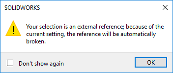
For Instance, Refer to picture below:
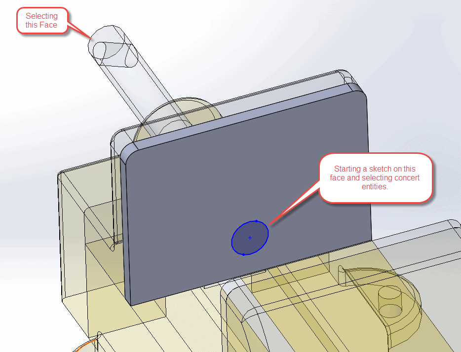
In the example above I edited the Jaw plate in context of the assembly. I started a sketch on the front face and selected the back face of the Vice Screw. I clicked convert entities which by nature takes the perimeter of the face and converts it into a sketch. I should have ended up with a sketch that contains offset entity relations which locks the sketch to the converted face allowing it to update if the diameter of the vice screw updates. The image below is a sketch with offset entities relations.
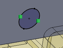
But, as you can see from the example, the converted sketch is still blue and does not contain any offset entities relations. At this point, I could define this sketch in any way I want.
To recap, the No External References command should be used in the case you want to avoid or do not want to create external references to existing parts in assemblies but want to use existing geometry to speed up the sketching process.
Thanks for taking the time to read and I hope this blog helped you understand what the command No External References does and how it should be used.
Greg Tutor, CSWE
Applications Engineer
Computer Aided Technology, Inc