SOLIDWORKS Configurations Part 3: Drawings
This blog is the third part of a configurations series. Starting where SOLIDWORKS Configurations Part 2: Using Configurations in Assemblies ended.
In this article, I give a brief overview of what types of drawing views can be created using configurations, as well as how to work with properties.
Aside from the conventional orthogonal views, (such as Front, Right, Top, etc.), you can assign configurations to these types of drawing views:
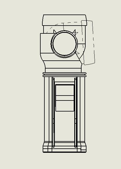
Alternate Position Views
This can overlay 2 or more different configurations to show alternate positions or movement of the assembly components.
Broken-Out Section Views
These views allow you to create a 2-D section view of each configuration to reveal the components within.
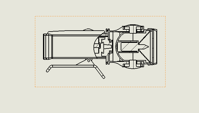
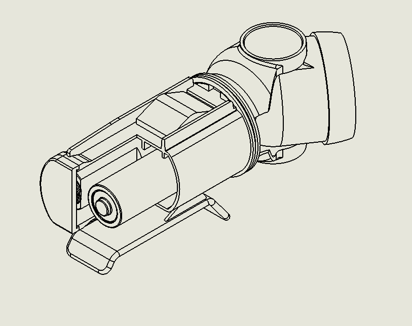
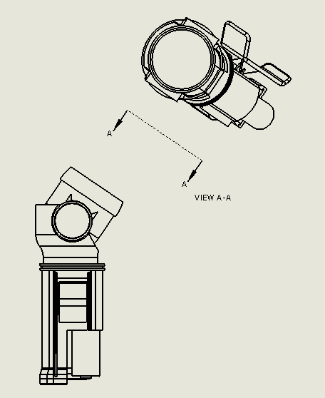
Assembly and Part Cutaway Views
You can also create a cutaway view of each configuration within an Isometric, Trimetric, and Dimetric drawing view to reveal the components within.
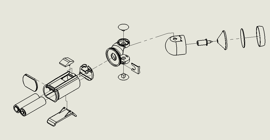
Exploded Views
These would allow you to create a drawing view for each explosion. You can create an exploded view for each configuration within the model.
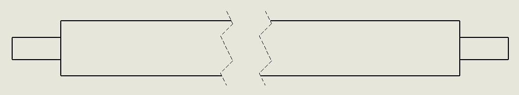
Model Break Views
For models that seem a bit too long for the sheet of paper, a Break View would resolve the need to save space on the drawing sheet. These can also have a configuration applied to it.
Auxiliary Views
Sometimes you need to show an auxiliary view, and these also allow you to assign a configuration to them.
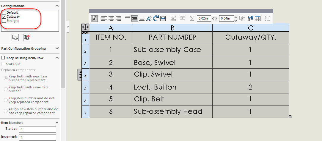
Configuration Specific Properties
When you have different configurations within a model, there is a chance that some properties will vary between them. For example, in a BOM table, you can apply the correct configuration to it as well as manually adding and removing rows, columns, etc.
That is going to conclude this portion of our blog. For more detailed information on “How To,” please review our training schedule or some of the training videos on my.Solidworks.com.
Stay tuned for more interesting articles from the rest of the team.
George Brañes
Support Engineer
Computer Aided Technology, Inc
www.cati.com