SOLIDWORKS: Design Intentionally with Non-Analytic Geometry
There are many ways to accomplish a desired outcome when designing with SOLIDWORKS. Be that as it may, Design Intent is just that; Intentional. In order for us to reach our end goal as efficiently as possible, we must be intentional with our chosen process.
While simple extrudes or cuts may be less cumbersome to mentally map out, non-analytic geometry, commonly achieved by Sweeps, can be a loftier goal. Speaking of Lofts, in this blog, I’ll use a rather specific example as to why a Loft may be a finer choice as opposed to a Sweep. As I previously stated, there are many ways to reach that finish line. However, will our design intent align with the capabilities of the initial feature choice?
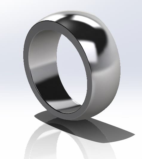
Let’s design a men’s ring. While a simple ring would not pose any feature obstacles in the design process, this ring will vary in thickness throughout its revolution meaning the size will not only change two-dimensionally, but three-dimensionally as well. To illustrate this concept, I have included a render of the final design below.
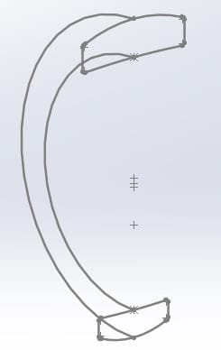
Now, how do we get there? Let’s first mention some specifics of our non-analytic features; the sweep and the loft. Sweeps only use one profile that can vary in size, with the assistance of guide curves, but not in shape. By this standard, we wouldn’t be able to make subtle changes in a given radius of curvature or arc length without affecting the shape as a whole. For this example, while the sectioned profile shape at the top of the ring is similar to that of the bottom, they still are not exact copies at different scales.
Lofts allow more than one profile to assist in changes of shape throughout the feature. Various shapes can be blended with a greater range of freedom and creativity. Additionally, constraints can be included where the feature begins, as well as ends. While another feature, known as a Boundary, provides even further control, we will focus on the aspects of the loft and the sweep in this example to better understand which of the two may be more advantageous.
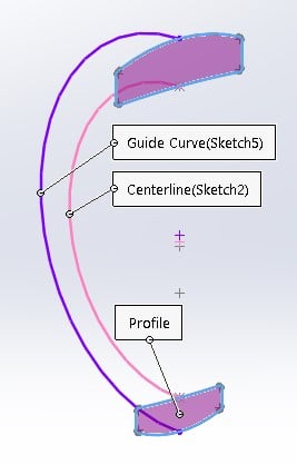
I’ve created the two profile shapes within the same sketch plane (right plane) to take advantage of a potential need for contour selections. This allowed for relations and ease of placement all on a single sketch plane. I then created the inside arc and the outside arc for one side of the ring (front plane).
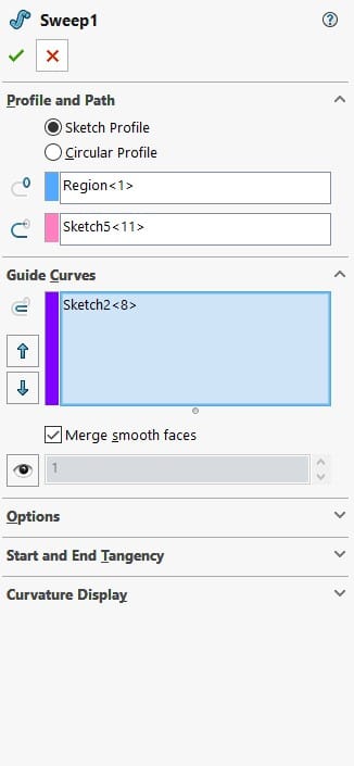
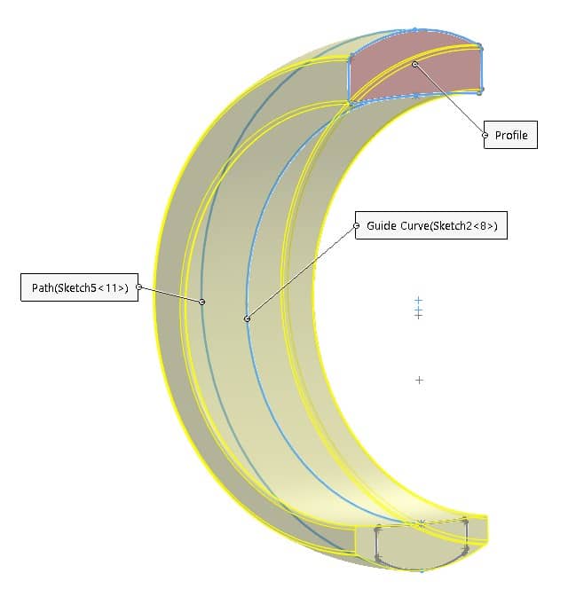
With the sketches complete, we can enable the sweep command and select our profile, path, and guide curve sketches. Upon making these selections, I notice that I cannot choose both regions of my profile sketch. This is the expected limitation of the sweep feature. Instead, I chose only the top profile sketch region and proceeded to select the path and guide curves.
Selecting the ‘Show Preview’ Option from the Property Manager, we see the above representation in the graphics area. Notice the highlighted profile shape hasn’t changed along the path as we would like. While this is still possible to achieve by use of the Sweep Feature, further geometry and minor mathematics are required. The addition of a ‘3D Sketch’ in the form of a helix would solve this problem. However, we would lose control over the resulting profile shape at the bottom of the model.
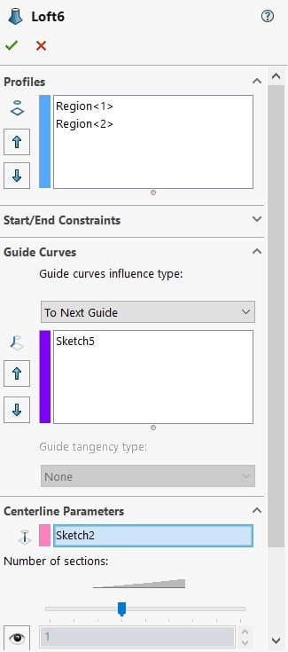
While we know our end result could be accomplished with the Sweep, let’s now see what the Loft Feature has to offer. The Property Manager of the Loft feature offers different selection options. Rather than choosing a profile, path, and likely guide curve(s), we instead have options for profile(s), guide curve(s), and a centerline.
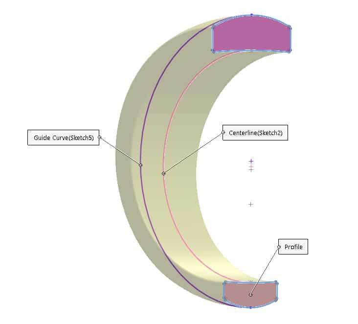
The Centerline Parameter for the Loft allows each section, or additional profile, to remain normal to the centerline while enabling the additional parameter for the number of sections from end to end. These sections will ultimately drive the overall shape of the loft. While this aspect is not needed for this example, we instead take advantage of the quick ability to gradually shape our model with one three-dimensional feature and strictly use two-dimensional sketches.
As shown above, we were able to create our desired ring shape with a single feature in less time and with fewer sketches than a sweep would call for.
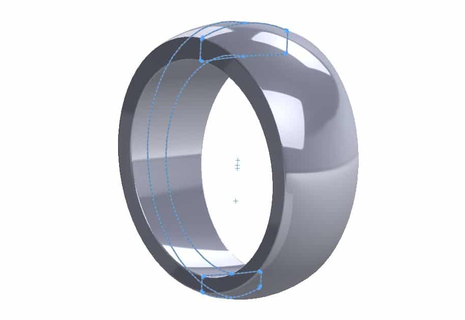
Finally, we see our completed model with our highlighted sketches after finishing with a mirror feature below. Understanding the advantages and limitations with each of these two features can help to produce finished models in less time. But, keep in mind, while there isn’t a best overall feature, there may be a better feature to use in certain circumstances!
Gabriel Rodriguez
Application Engineer
Computer Aided Technology, LLC

 Blog
Blog 