SOLIDWORKS Electrical 3D: How to Create Custom Ducts or Rails
Creating Custom Ducts or Rails
In this tutorial, I will be showing you how to create a custom rail with the correct intelligence to integrate into your electrical projects. The method of creating the rail will be equivalent to creating a duct with only a couple differences.
These steps are valid for both Ducts and Rails.
1. Create a new part in Solidworks
2. Define the profile sketch of the rail or duct as desired and extrude the profile: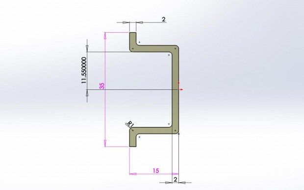
3. In the configuration tab rename the default configuration to EW_CONFIG:

4. Rename the extrude depth dimension to EW_DEPTH:

5. Rename the extrude feature to EW_EXTRUDE:

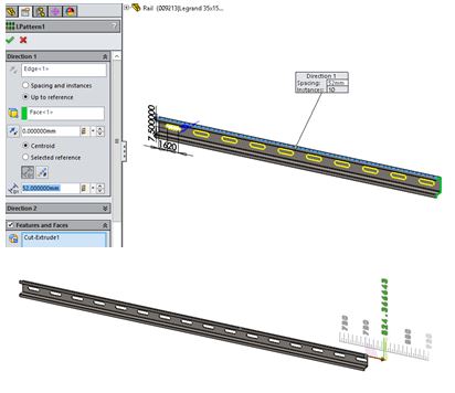
Note: In Solidworks 2015, try out the new patterning feature to auto-generate your fastener holes when the rail expands in length!
6. Let’s add some smart mates to the rails as well. Go to Solidworks Electrical > Electrical Component Wizard:

7. Pass the first menu. Select “Create TREWBACK Mate reference”:
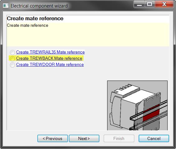
*Note*: It is important to first create the back plane reference BEFORE the rail mate references. This will ensure that the smart references will work correctly in the SOLIDWORKS Electrical 3D assembly environment.
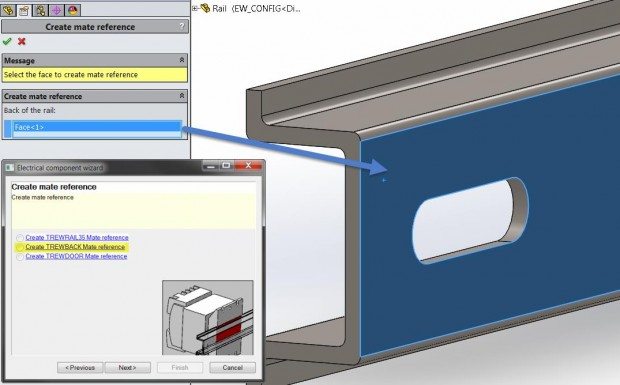
8. Now select “TREWBACK Mate reference” and select the back of the rail:
9. Apply the mate. Now, back in the menu select “Create TREWRAIL35 Mate reference”. Select the top and front face of the rail. Note that this must be at a 90° angle:

10. Done! Save the part. We will now add references in SOLIDWORKS Electrical to use this new rail.
11. If you are designing a wire duct, you’ll need to do some additional steps:
a. Add a 3D sketch line through the center of the duct.
b. Convert the 3D sketch line into a routing line by going to SOLIDWORKS Electrical > Create Routing Path:

c. This will give the duct the intelligence needed to auto-routing wiring lines.
Once the new part has been created they can be inserted into the SOLIDWORKS Electrical assembly by first attaching the part to a manufacture:
12. Go to SOLIDWORKS Electrical > Manufacturer Parts Manager. Select “Boxes, cabinets”, then click on “Add part”:

13. With the part properties, you must provide a part # and manufacturer. Under the Illustration field, click in the open “…” field and browse to the newly created rail or duct part:

a. Note, if you scroll down you will need to set the width, height, and depth values of the part. In this case:

b. These values will have a few limitations. The depth of your rail part will be defined as a minimum. The rail can be expanded to any value above 520 as this was created with the original rail. Checking “Adjustable” will allow this change to occur using the electrical 3D feature. In creation of your rail, be aware of this limitation or create an original model at a smaller depth scale.
14. Select OK and you’re done! The part will now have the intelligence to use “Change length of Rail or Duct” in SOLIDWORKS Electrical 3D.

Post By: Brian Do | Electrical Product Specialist