SOLIDWORKS Electrical: Defining PLCs with Racks and Modules
The PLC manager is accessed through Project > PLCs. It allows you to add and modify PLCs in the project. You can add PLCs individually, or you can set them up as Racks with Cards (modules). In this article, I’ll walk through setting up a PLC with a rack and modules. We’ll focus on how to set up the slots of the rack and specify in which slots the cards are installed.
Setting up the PLC
First, click on Add PLC, and after modifying and accepting the properties for it, add a rack to the PLC using the Add Rack button. In the rack properties, the slot field defines the number of available slots in the rack. Setting it to 5, we see 5 available slots appear in the PLC manager. Without slots defined, those do not show up.
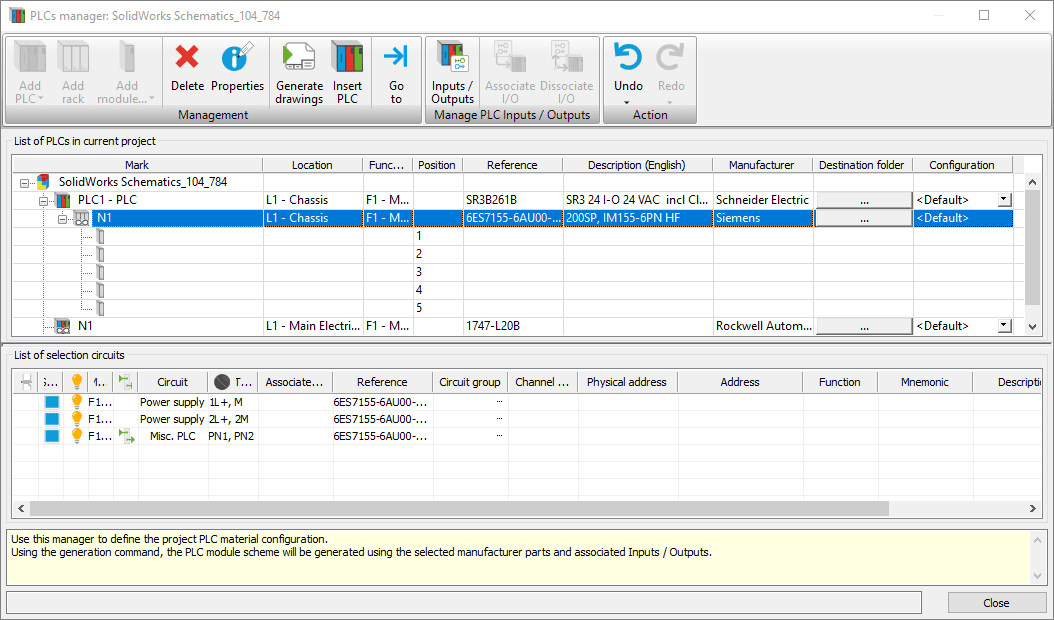
Now let’s add a PLC module. Select the slot you want to place a module into, and click on add module.
Pick a part from the manufacturer library.
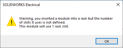
The manufacturer parts for PLCs have the same available property fields (position, slot, etc) so you can define the defaults. For modules, the slot field defines the number of slots that it occupies. However, if they are blank then you may get a warning popup as you select it. In this case I picked a part that doesn’t have the number of slots defined. So I got the warning below that it is going to assume it only uses one slot.
Here you see the result:
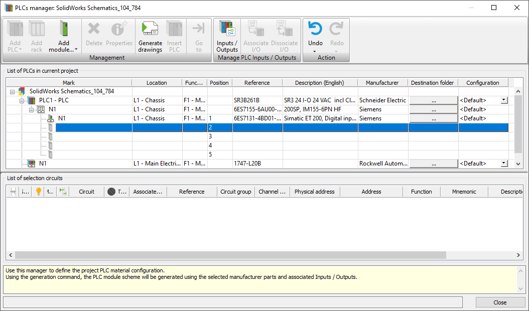
So module N1 is in Slot 1. Since the slot field was empty in the manufacturer parts properties, it assumes it only takes up that one slot. However, if I go to the properties of the module, and in the slot field, put in the number 3…
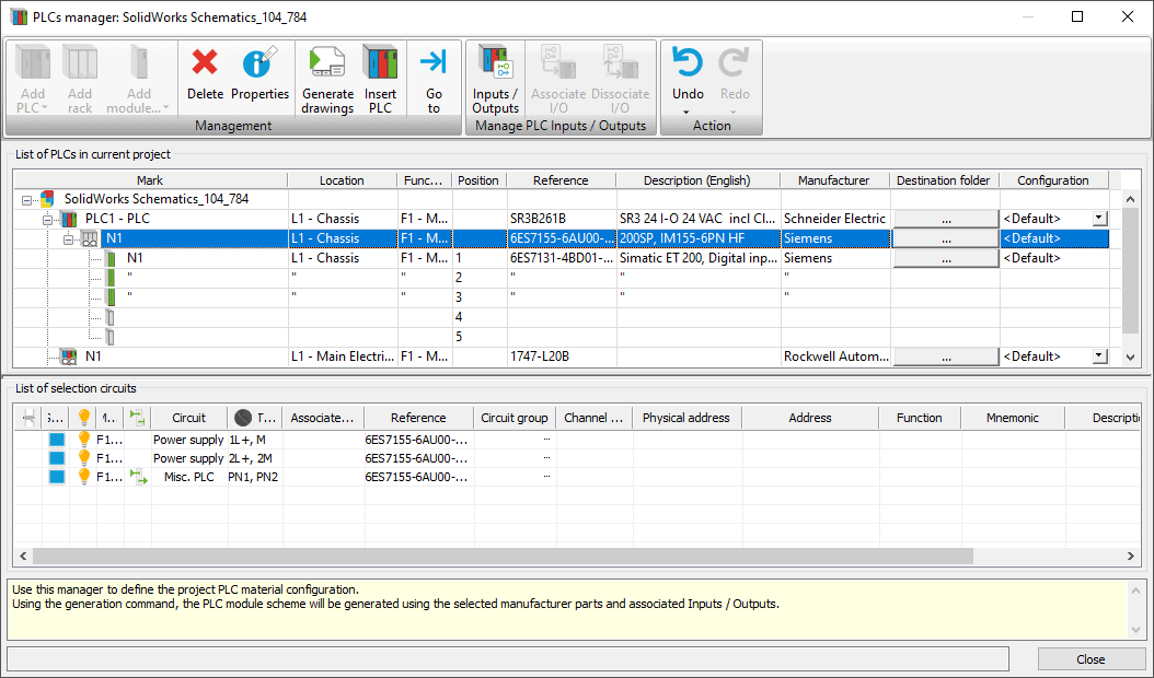
…you can see it now takes up 3 slots in the rack. The Card Position field was set to 1, so it starts in the first slot. If I changed that to 2, then it would take up slots 2-4.
If I put in another module in slot 4, and say it takes up 2 slots, it looks like this.
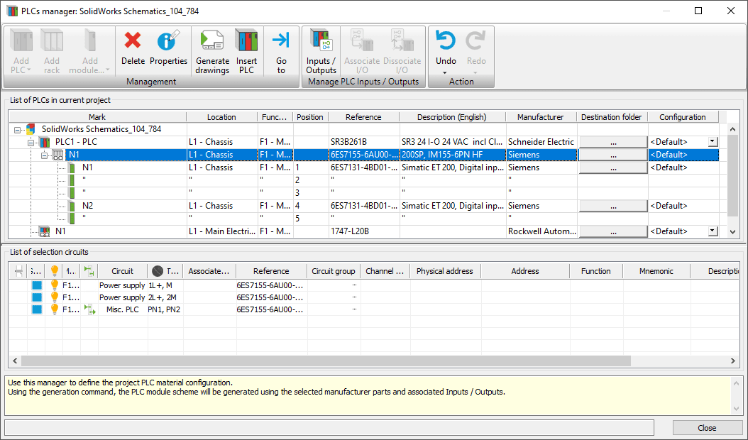
It is that simple to set up a PLC before inserting it into the schematic. When you select insert PLC from the schematic ribbon menu you will just select which one you want to insert, and place the symbols.
Something to watch out for with racks and modules
I will point out that it is possible to break it. I have submitted a bug report for this, but I wanted to let you know in case this happens to you.
If I define module N2 as taking up 3 slots, it adds another slot to make the rack 6 slots total. Technically this is not able to happen if this rack really only has 5 slots. No warning shows up, which isn’t ideal, but at least it isn’t totally broken. Just be careful about the possibility of placing components that take up more space than the rack allows.
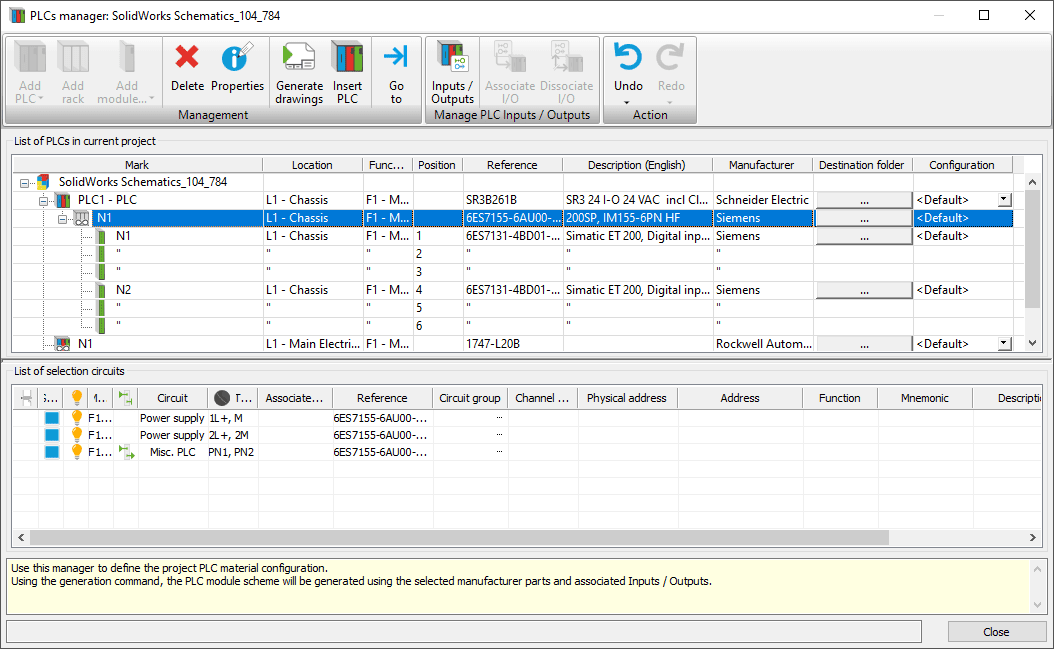
Let’s really break it. I’m going to change the number of slots back to 2. Then, change the card position to 3. Slot 3 is already taken up by module N1. Here’s what happens.
If I change to 3 and then click outside of the field, then I get an error that the slot is not available, and it changes it back to 4. This is good as it keeps me from making a bad mistake.
BUT, if I change it to 3 and click ‘ok’ without first clicking outside the field, then it accepts it.
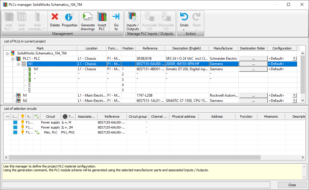
As you can see, I don’t see module N2 in the PLCs manager anymore. The only way to get it back is to fix the N1 module properties to take up less slots, so that N2 is allowed into slot 3.
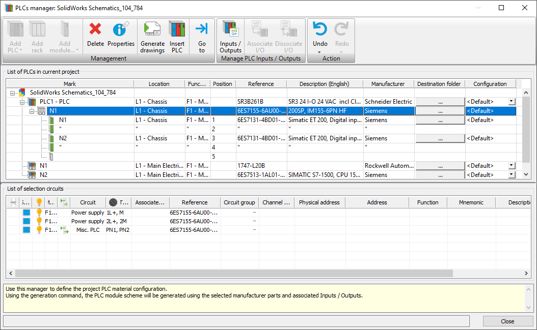
These bugs will hopefully get fixed soon, but in the meantime it shouldn’t be too hard to work around them. Overall the PLC manager is a powerful tool to set up your PLCs before placing them in your project.
Brian Cooke
Sr. Application Engineer Specialist, Electrical
Computer Aided Technology, Inc.

 Blog
Blog