SOLIDWORKS Electrical: Process and Instrumentation Diagrams, P&IDs
Process and Instrumentation Diagrams, P&IDs
One of the most unknown features in SOLIDWORKS Electrical is the ability to create P&ID schematic diagrams. Process and instrumentation diagrams consist of many different mechanical elements for process flow. A complete P&ID schematic will show the connection of the process equipment and all of the instrumentation used to control it. The data within these designs can vary from simple to complex but can contain elements such as names of the equipment, control inputs and outputs, process piping, control systems, and much more.
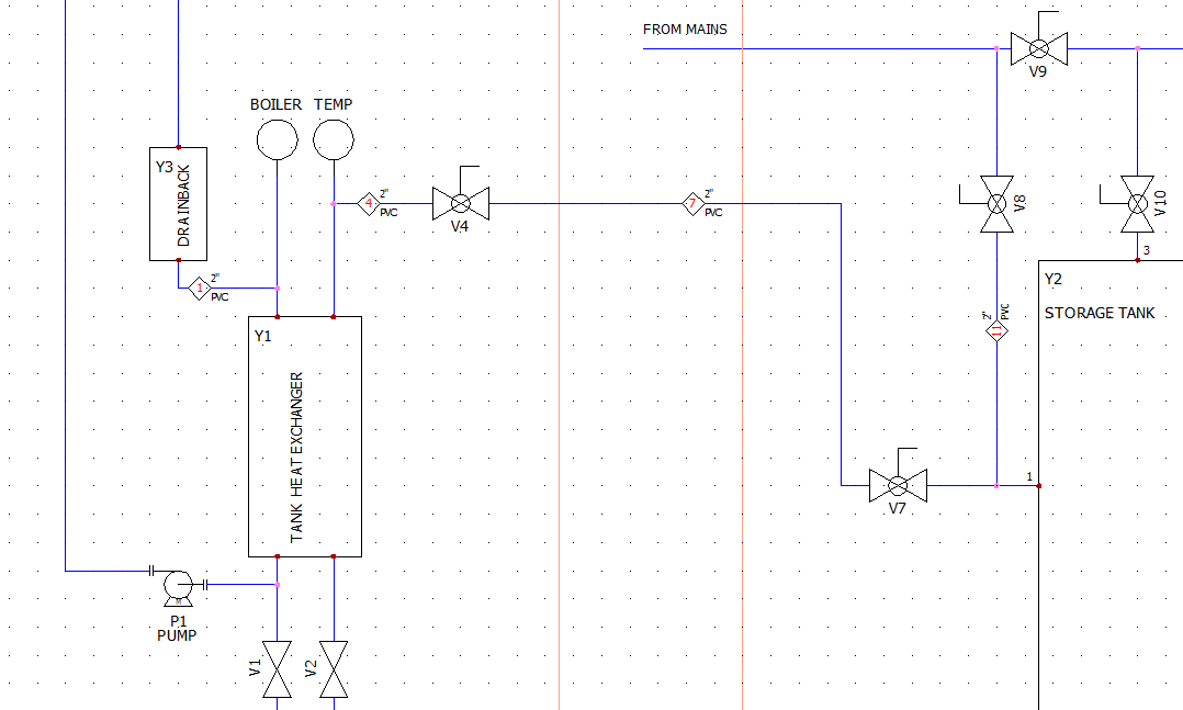
Simple P&ID example
SOLIDWORKS Electrical is designed to help organize this data in P&ID drawings and combine these drawings directly with the electrical schematic drawings as well. The combination ability can connect elements from control schematic to power drawings to the P&ID design. This allows us to have a uniform system and with the reporting tools in SOLIDWORKS Electrical, we can generate output documentation.
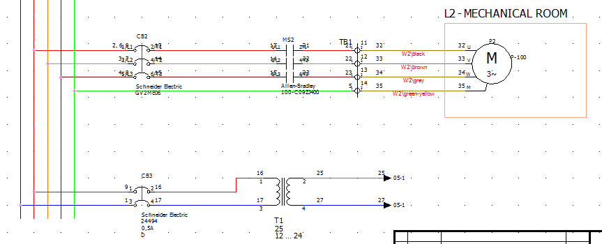
Power Schematic Example
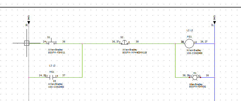
Control Schematic Example
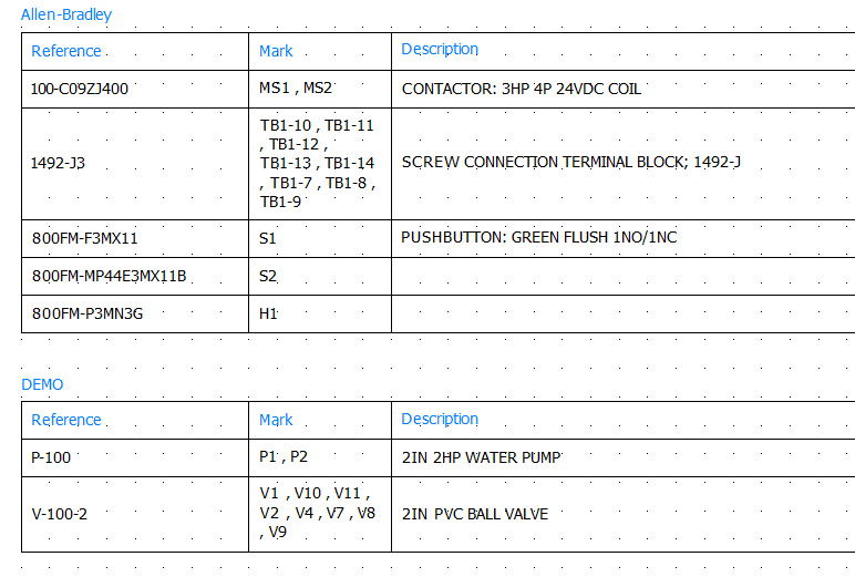
Each component element that is added in your project can be developed in any of the above drawings and then used in reports to create a complete bill of materials as well as reports such as wiring and piping reports. By having a uniform system, we can easily make revision changes in one area of the design and have the information propagate to reports and other schematics.
SOLIDWORKS Electrical has many powerful functions and tools to help you create designs and documentation. With P&ID designs, SOLIDWORKS Electrical can keep you designing quickly and efficiently while keeping your deliverables organized and up to date!
Brian Do
Application Engineer
Computer Aided Technology