SOLIDWORKS Electrical: Sub-Components
What is a sub-Component?
When you place terminals using the insert terminal command in SOLIDWORKS Electrical, it will automatically add terminals to an overall terminal strip. In this case the terminal strip is the master component, and the terminals are the sub components.
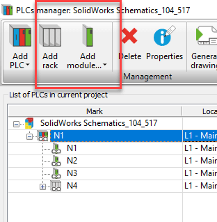
In the PLC manager, you can create a PLC and then add plc cards, racks, etc to the PLC. There is an overall master component mark, and then the sub component PLC parts.
This same type of hierarchy can be achieved with more than the terminals and PLC components. However, it isn’t as readily apparent.
How to create sub-components
When you place regular symbols on the page, you do not have the capability to designate it as a sub-component. You can associate with existing components, and end up with parent-child symbol relationships, but it is still the same level component hierarchically. All the symbols will receive the same mark (i.e. K1).
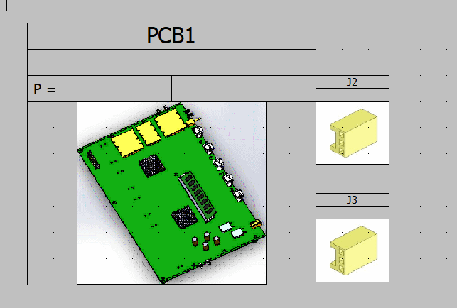
Let’s say you have a PCB and want to represent the connectors on that PCB. The connectors have their own marks: J1, J2, P1, etc. Let’s look at how to place those symbols and make them associated with PCB1, but maintain their unique labels.
Method 1 – Placing symbols first.
I will show using a line diagram, but the same method can be used in a multi-line schematic.
-
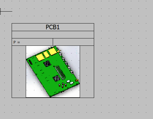
- Place the PCB symbol to create the PCB component PCB1
-
- Place the connector symbols. If you already have other connectors in the project with the marks that are also on the PCB, then the marks will not be correct at this step. Place them with the incorrect marks.
-
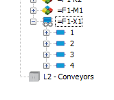
- The component tree will show this as 3 different components. Click and drag the connector components into PCB1.
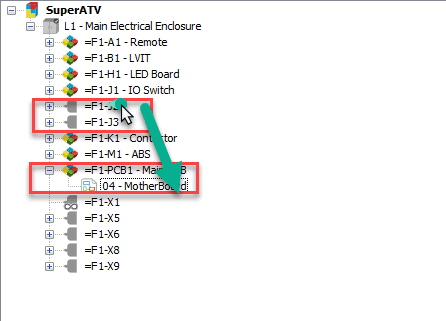
Becomes…
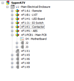
-
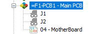
- Modify the sub-component marks. They can now be cycled to start at an order number of 1.
Method 2 – Set up component tree first
If you don’t like having to modify the component marks after placing the symbols and organizing the tree, we can set up the tree as a first step. Then place the symbols.
- Place the PCB symbol to create the PCB component PCB1. Or create it in the component tree using the right mouse button menu > new > component

- Right click on the PCB1 component in the component tree. Select new > Connector. Pick your root mark. The order number will start at 1, or you can increment it to the appropriate number to match what exists on the PCB.
- Repeat as necessary until your tree has all of the PCB connectors.
- Right click on the sub-components and insert symbols.
These components will appear in the Bill of Material as “Master Comp” – “sub-comp.” So in my example, it would be PCB1-J1, PCB1-J2. That naming scheme will also appear on your symbols if you are using the #TAG attribute. If you use the #SHORT_TAG it will only display the sub-component name on the symbols.
Having component hierarchy can be very useful for things like off the shelf components that have connectors you need to connect. They can also be useful for items such as fuse blocks that hold multiple fuses. The connection points have to be on the 3D fuse block, for accurate wire representation, but you don’t want 3 fuses all labeled F1, so you could have a master component as a fuse block, and then insert fuse symbols with no circuits, each labeled uniquely, as a sub component of the fuse block.
Brian Cooke
Application Engineer
Computer Aided Technology, LLC