SOLIDWORKS Electrical: Taking the Guesswork Out of Terminals
SOLIDWORKS Electrical has a robust terminal strip manager and terminal strip drawing generator; however, there is not a lot of training or reference content on the many functions and features available within the tool. In this blog, we will dive into some common features of terminals in SOLIDWORKS Electrical.
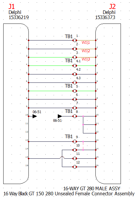
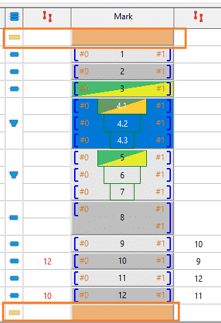
Above you can see several terminals in a terminal strip. These are grouped by different use cases that we will work through.
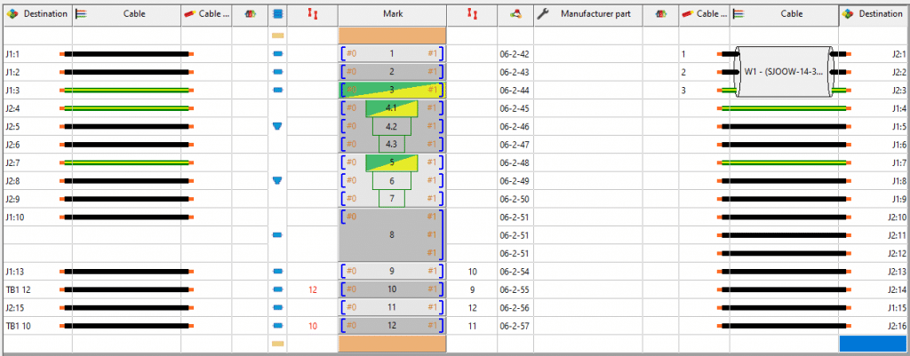
In SOLIDWORKS Electrical, we have a terminal strip manager where we can review and edit our terminal properties, connections, and outputs. This gives us a great summary of all the terminals in our project through one interface.
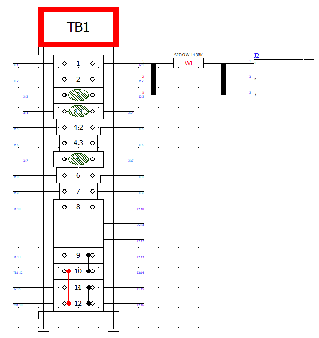
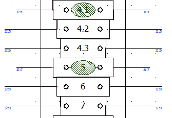
We can also generate drawings of our terminals automatically. This can be done upon right click of a terminal or through the “Generate Drawings” feature within the terminal strip manager. These drawings are rule based deriving from an editable terminal configuration. The main styles for terminal strip drawings are tabular or graphical. These can both be drawn vertically or horizontally. We will focus on the vertical, graphical style for this blog as it is more easily comparable with the schematic.

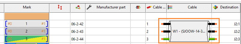
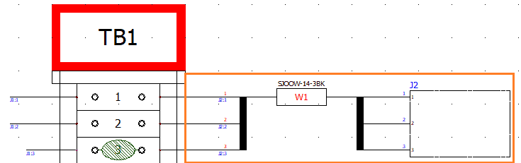
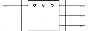
In our first grouping of terminals, we have simply inserted three terminals and associated a 3-conductor cable to them. Item of note here is that the cable can be optionally included in the terminal strip drawing and the connected object will show if completely connected via the cable. You may have also noticed that some terminals have a ground symbol association to them. This is automatically set every time a wire style that has “Protection” in the conductor type is connected to a terminal.
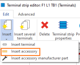
Within the terminal strip manager, we can also add accessories such as endcaps or dividers. These will insert nicely with the terminal strip in a drawing or even in a mechanical assembly. If you want to add manufacturer components outside of the stack up such as bridge components or hardware, this can be added at the component level and filtered in reporting as needed.
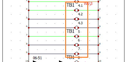
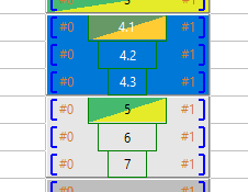
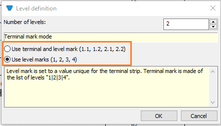
For another terminal use case, let us have a look at multi-level terminals. These can be numbered using terminal and level marks or the mark of the level as determined by the first attached manufacturer part. A terminal can be set to multi-level upon right click on the schematic or terminal strip manager. You can also simply assign multiple terminal symbols to one component to make a multi-level component.

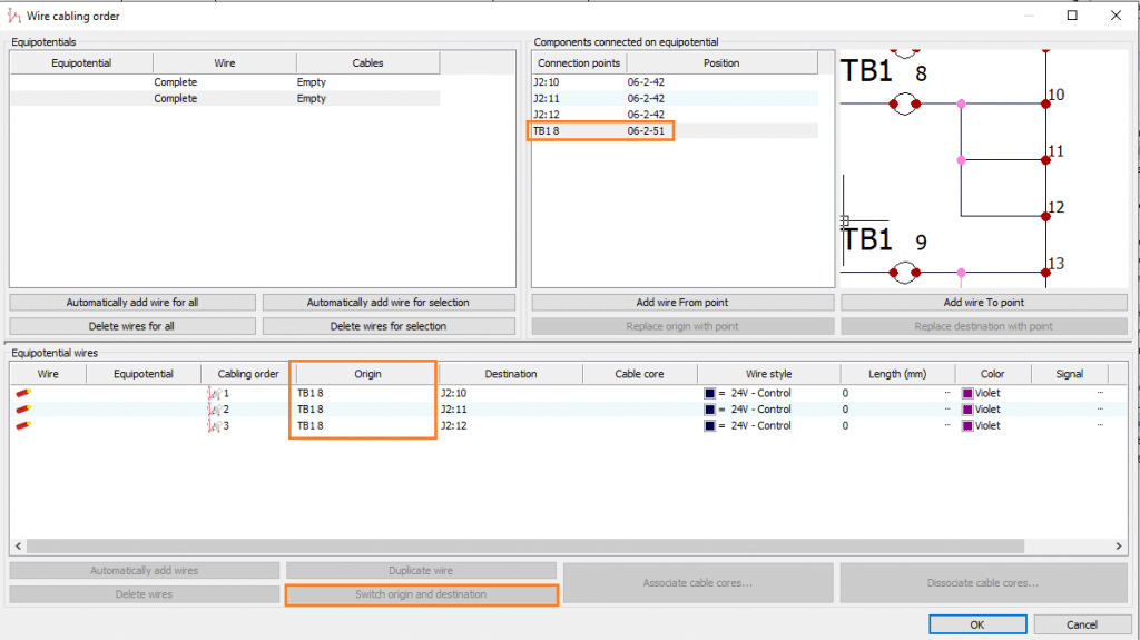
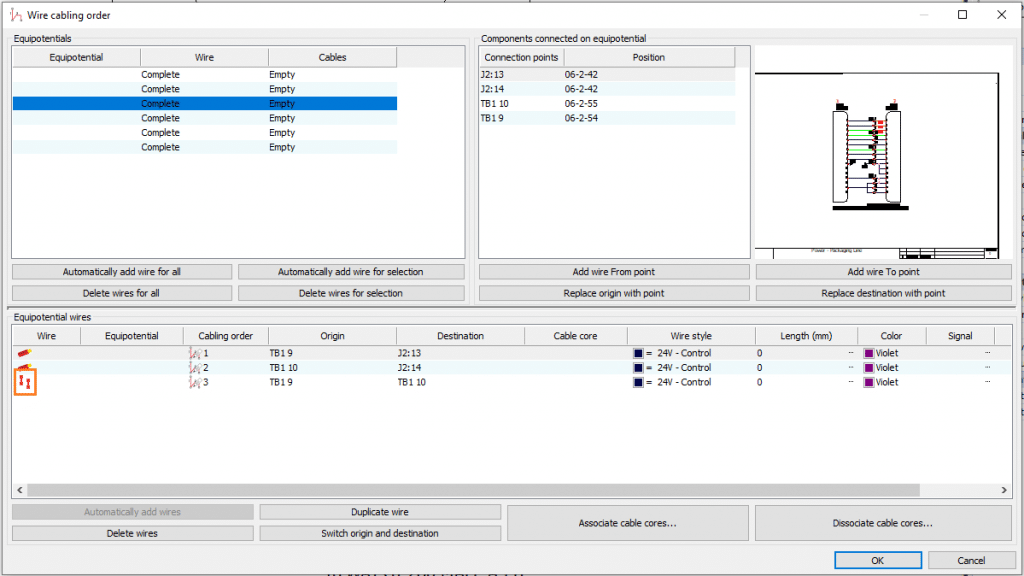
Our next terminal use case is connecting several wires to one terminal. This can be done like any other equipotential connection. The key thing here is that the wire cabling order needs to be reviewed. This can be done upon right click of the desired equipotential. I like to maintain the “Origin” as my terminal connection for each wire. This can be edited with the “Switch origin and Destination command” and dragging the desired connection point over the “Origin” field in the Equipotential wires list.
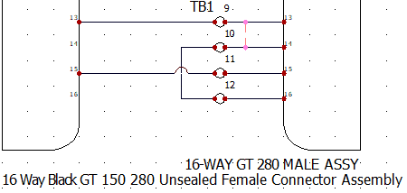
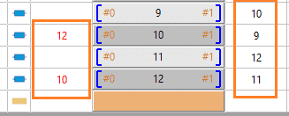
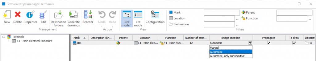
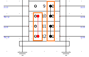
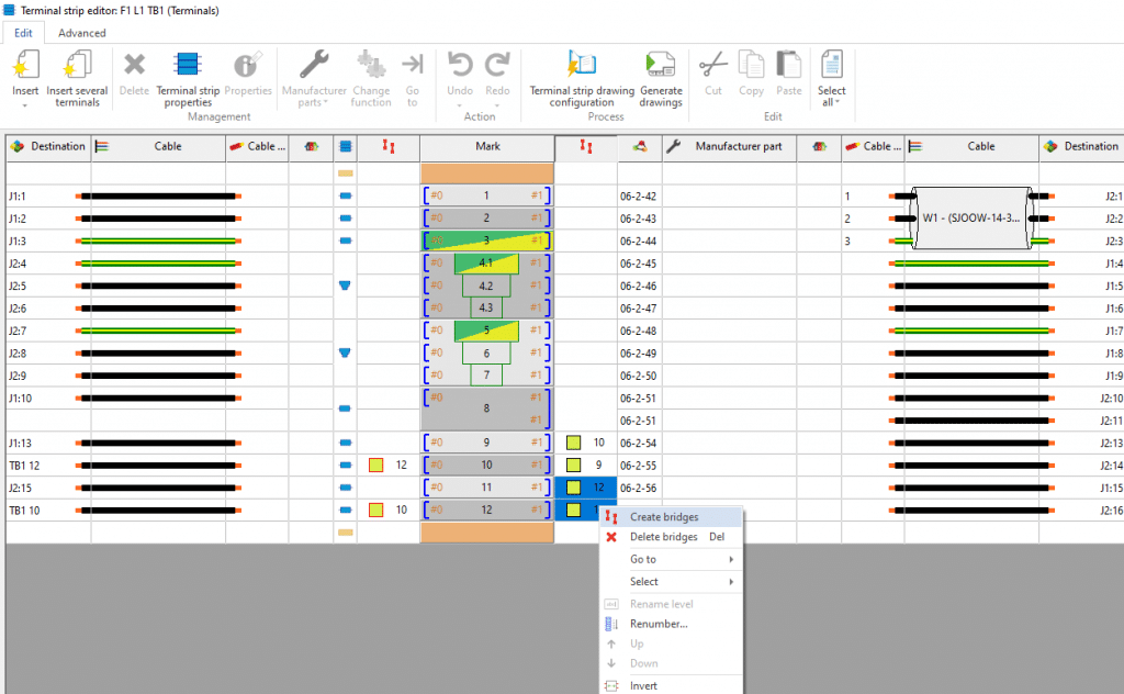
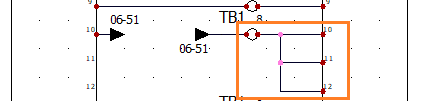
For our last terminal use case we will discuss bridging. Bridging can be performed automatically or graphically on the schematic, or behind the scenes in the terminal strip editor. Automatic bridges are treated differently than the latter two and can be turned off altogether if desired. An automatic bridge is an assumption that a bridge needs to be created for any terminals that have connections with equipotential marks that are identical. By default, these show up in red in the terminal strip manager and drawing. Drawn connections can be set as a bridge instead of as a wire. This can be done upon right click of the connection in question. The key here is that the wire cabling order is reviewed to ensure the bridge is going between the desired connection points. Lastly, bridges can be setup in the terminal strip. Simply multi-select the bridge columns you want to connect and select “Create bridge.” The schematic bridges and created bridges function the same in the terminal strip drawing and manager.
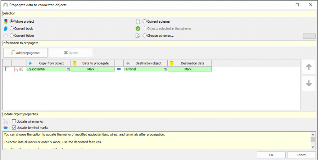
Some documentation standards require that terminals be marked with the connecting equipotential or that a wire be named based on a connected device. This can be performed by the “Propagate data to connected objects” command. Here, for example, we can specify that the wire equipotential mark propagate to the terminal mark as shown above. It is also important to have “Update terminal marks” checked for this case.
With automated terminal strip drawings, we can make cabinet or field wiring much easier. Instead of flipping through and following connections from sheet to sheet, we can review a summary of every terminal connection at a wire and cable level. With SOLIDWORKS Electrical, not only can we parametrically generate these drawings, but we have a whole host of documentation options and workflows to ensure that our projects are communicating the proper intention of the designer. Yet another way we can improve our project standardization and documentation for manufacturer or for delivery to client.
Mark Talbott
Sr. Application Engineer Specialist, Electrical
Computer Aided Technology, Inc.