SOLIDWORKS – WHAT IS FACE CURVE?
Face Curve is a mesh that lays out the underlying U-V curves of a face. The mesh density can be increased or decreased. You can specify a mesh of evenly spaced curves or a position that creates two orthogonal curves. When using the mesh selection, it creates a series of 3D sketches forming a mesh on that face. Let’s get started.
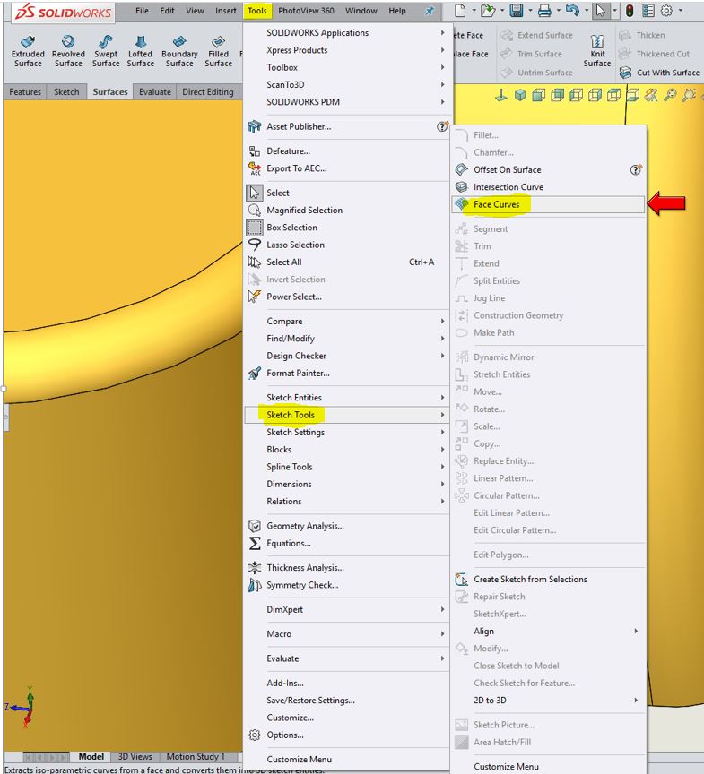
You can find this command under Tools, Sketch Tools, Face Curves.
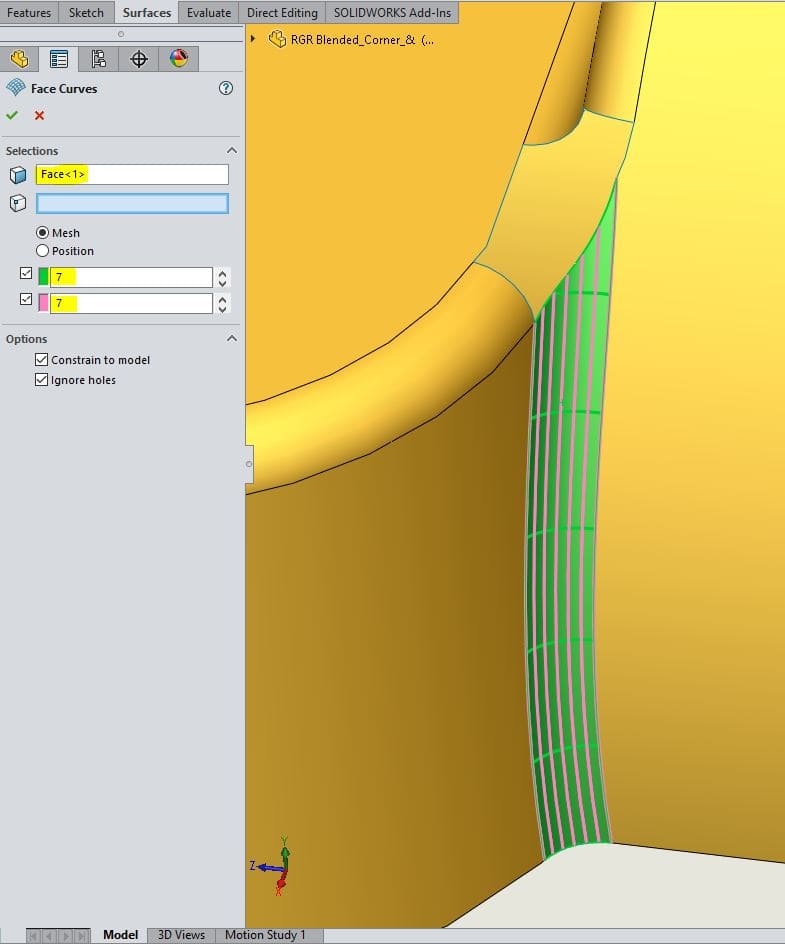
Let’s take a look at the mesh part of the command. This will evenly space the mesh/curve.
Select a face and click the mesh radial button. Here you can control the mesh by increasing and decreasing the direction 1 and 2. You can turn the direction’s on and off by clicking the tick box.
Under Options:
Constrain to model – When selected, the curves are updated if the model changes.
Ignore holes – Use for imported surfaces with internal gaps or loops. When selected, the curves are generated across holes as though the surface were intact. When cleared, the curves stop at the edges of holes.
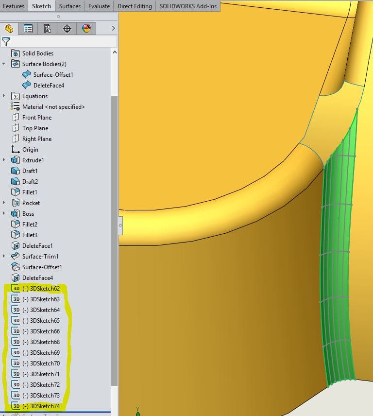
Hit the green check mark and you can see a 3D sketch was created for each mesh/curve. NOTE: If you are working in an active 3D sketch and use the Face Curve within, those 3D sketches will be absorbed in the active 3D sketch.
Now let’s look at the Position selection, click Face Curve, select the face and select a vertex, this will automatically select the Position option.
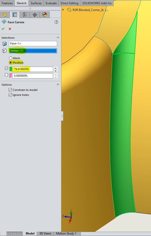
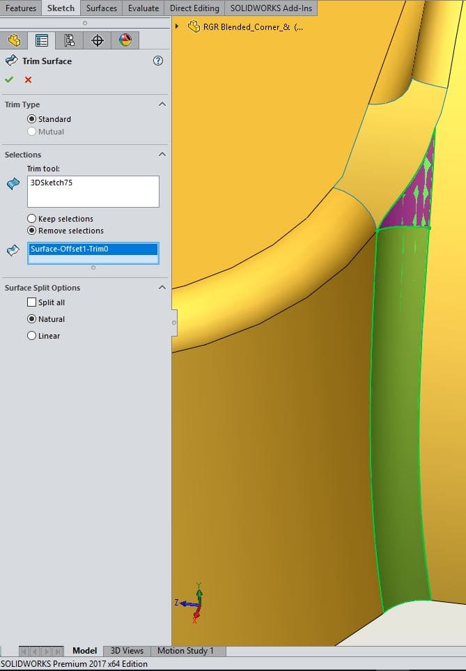
We can now use that 3D sketch as a Trim Tool in Trim Surface command. In this case, I want to remove the top portion of the surface.
There you have it. Face Curve, check it you.
Roger Ruffin
Sr. Application Engineer
Computer Aided Technology