SOLIDWORKS Flow Simulation: Lid creation for non-planar faces
What are lids and why do we need them?
SOLIDWORKS Flow Simulation supports two main study types, internal (flows bounded by outer solid surfaces, e.g. tanks, office space, etc.) and external (not bounded by outer solid surfaces, e.g. flow over a wing). Internal flow studies often contain geometry that have inlets and outlets. Flow Simulation requires that these inlets and outlets be bounded by a face. These bounded faces will then contain the info necessary to describe the flow for the inlets and outlets. We bound the inlets and outlets using lids.
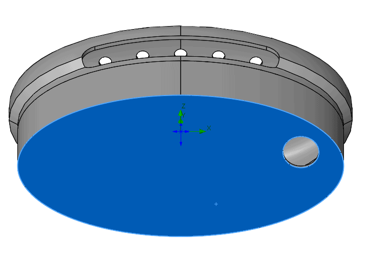
Below is a model that we will be looking at in this blog. Each hole in this model will need a lid. Notice the hole in the blue face. We will create 2 lids, one automatically and one manually, and we will start with the hole in the blue face (see pic below).
Automatically create lids: using the Lid tool
Fortunately, SOLIDWORKS makes this very easy by providing a lid tool. The lid tool allows the user to specify a thickness. Avoid creating lids too thick or too thin; generally, the lid thickness should be the same thickness as the walls in the model around it. However, this lid tool has limitations. Specifically, lids can only be created on planar (flat) surfaces (see pic below).
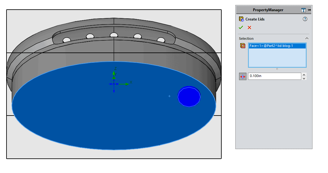
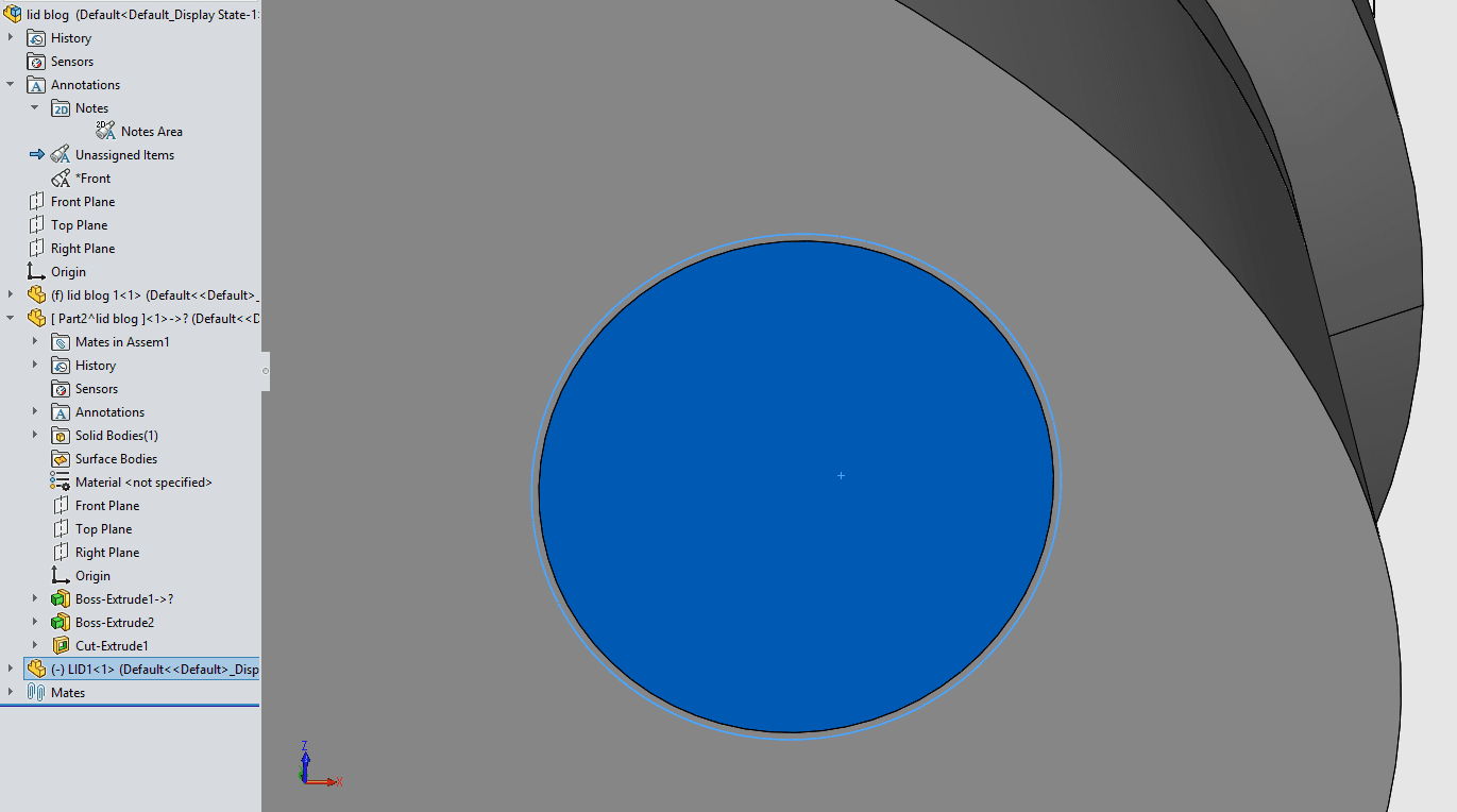
The lid tool then creates a part in the assembly called LID1. This lid is created with an interference in the model as demonstrated in the picture below.
Once the lid has been created, the user must apply a flow condition to the inner face of the lid. The type of conditions supported include velocity, mass flow, and environmental pressure among others. Once again, this lid tool works for planar faces only!
Creation of custom lids for curved faces
Curved surfaces can be complex, so how do we accomplish this? The steps to make a custom lid are easier than you may expect. Let’s make a lid for the part pictured below!
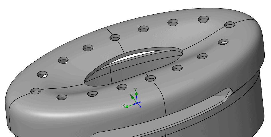
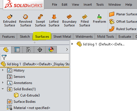
The first thing we do is open the part. Secondly, we need to gain access to the surface tools, I typically use the Surfaces tab in the command manager. Please note that this part needs multiple lids, we are focusing on only one. We could make a new part for each lid like the lid tool does but that is time consuming and not necessary.
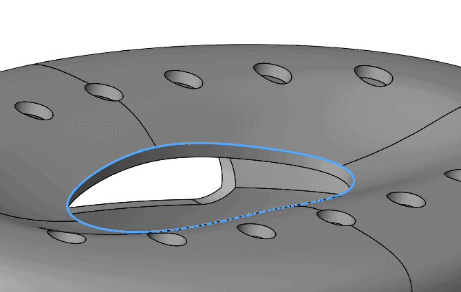
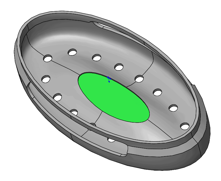
Let’s create a lid for the hole shown below with its edges highlighted in blue. We will make use of the Filled Surface command.
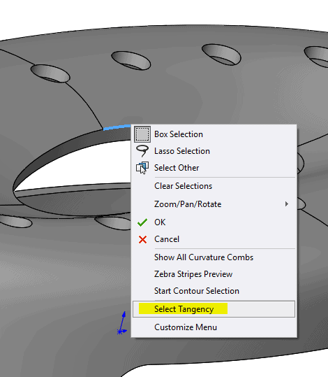
Select the Filled Surface command, right click on the edge, and then use select tangency. The edge can be selected one segment at a time and, for this edge, that would be easy because it only has 4 segments. However, select tangency is even easier, especially if the hole has many edges.
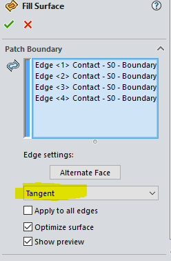
Change the edge settings to tangent (shown in pic below), then click the green check mark. Just like that, SOLIDWORKS created a new surface body (contains 0 thickness).
We need to add thickness to this body, but we are going to do something unexpected first. Use the Extend Surface command to create the interference (remember the lid tool also creates an interference). Interference does not need to be large, so 0.050” is usually more than enough. SOLIDWORKS simulation users are likely in the habit of removing interference, but interference is acceptable in Flow Simulation. Not only is interference acceptable, but it is a best practice for creating lids because we need to avoid edge to face contact between bodies. SOLIDWORKS will see any edge to face contact as open for fluid flow.
Finally, use the Thicken command to give the surface body a thickness resulting in a solid body. If we select merge, then the lid combines with the body of the part. For Flow Simulation purposes, merging the lid bodies with the main geometry, or not, will have no effect on the simulation.
In the Flow study you will then use the inner face of this lid for a flow condition (green face in picture below).
Matthew Fetke
Application Engineer – Simulation
Computer Aided Technology, Inc