SOLIDWORKS: The INTERSECTion Between Solid and Surface Modeling
I was visiting a colleague recently who was tasked with adding counterbores and countersinks, among other things, to his model. You may be thinking “that does not seem like a blog worthy topic, it’s easy to do with the Hole Wizard, and, most recently, the Advanced Hole tool!” The challenging part was the faces were non-planar and the holes were not cutting all the way through the part. Maybe you have run across this issue before as well.
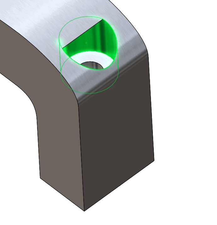
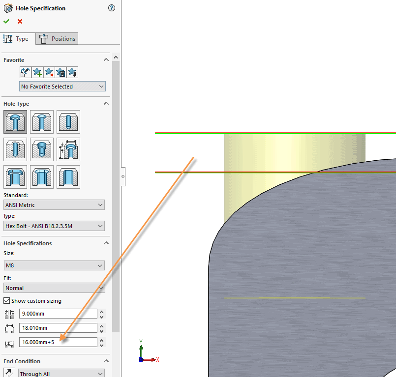
The most intuitive way to tackle this problem would be to create an offset plane above the contoured surface, and create the counterbore there. Countersinks would present a bigger challenge in this instance. Creating an offset plane would work in creating the desired shape on your model. However, you would have to do some extra math to get the correct depth for your counterbore. In turn, your Hole Callout would have a depth from that extended plane and not your intended cutting plane.
A better way to address this issue would be to use surfaces to remove the portion you do not want. SURFACING?! That can sound daunting for those who have never ventured into using them, but hear me out, it is a pretty easy technique, and is what SOLIDWORKS is doing behind the scenes anyways!
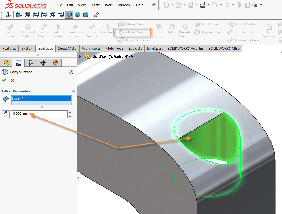
First, under your Surfaces tab, choose Offset Surface, and choose the appropriate face. Then, set your offset value to Zero. This will essentially create a surface copy of the face.
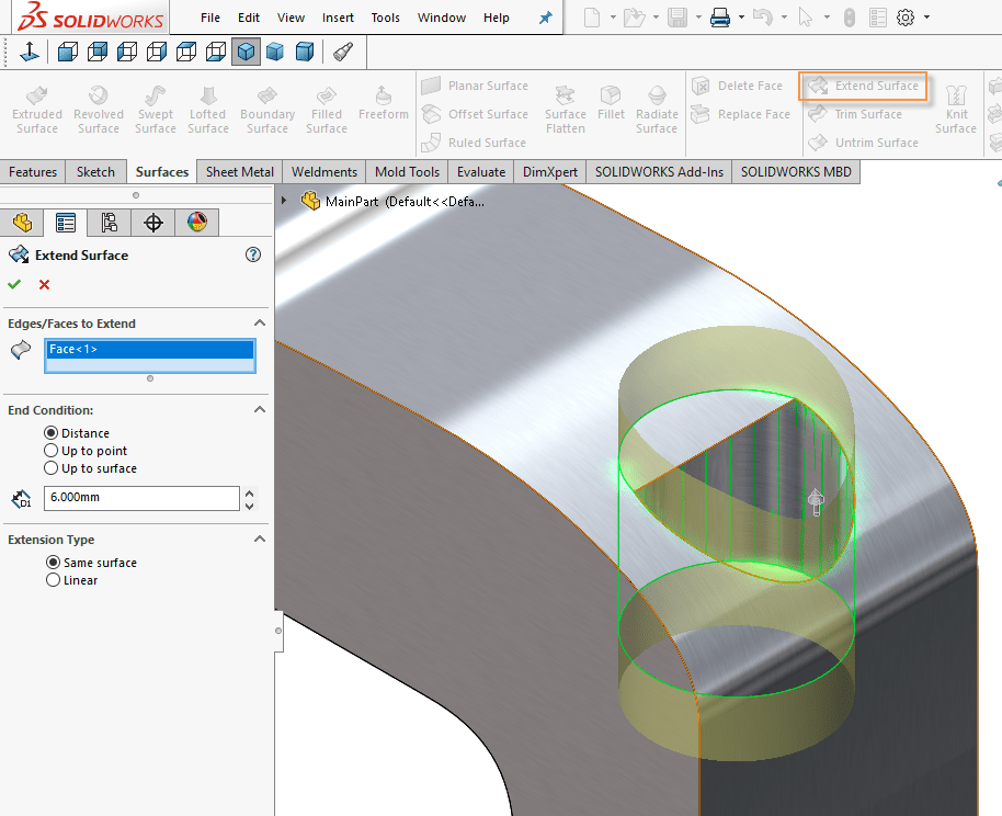
Then, choose Extend Surface, and select the new surface body that you created. The value for this does not really matter as long as it extends past the face you want to cut.
You will then use the Intersect command to create (and remove) new bodies from the solid and surface bodies you have.
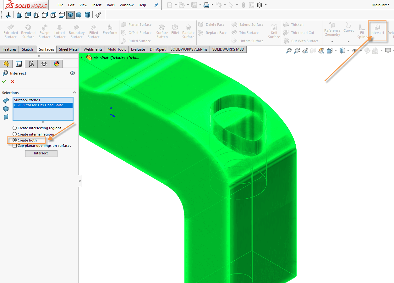
With the Intersect command chosen, select the bodies you want to use and, in this particular case, choose to create both intersecting and internal regions, by selecting the Create both option.
The model is now split into multiple regions based on the intersect and you can choose which ones you want to remove and keep.
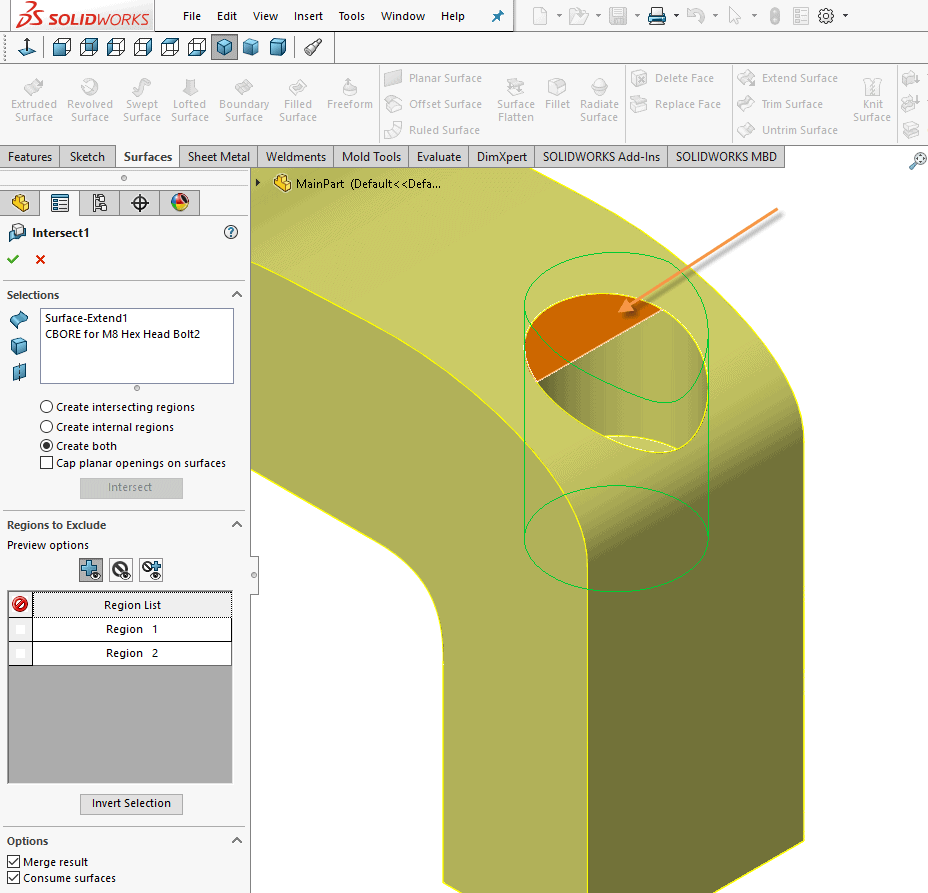
Now, simply choose the region you want to remove and check the box to Consume surfaces and you are left with the desired cut with the callout depth from your intended plane.
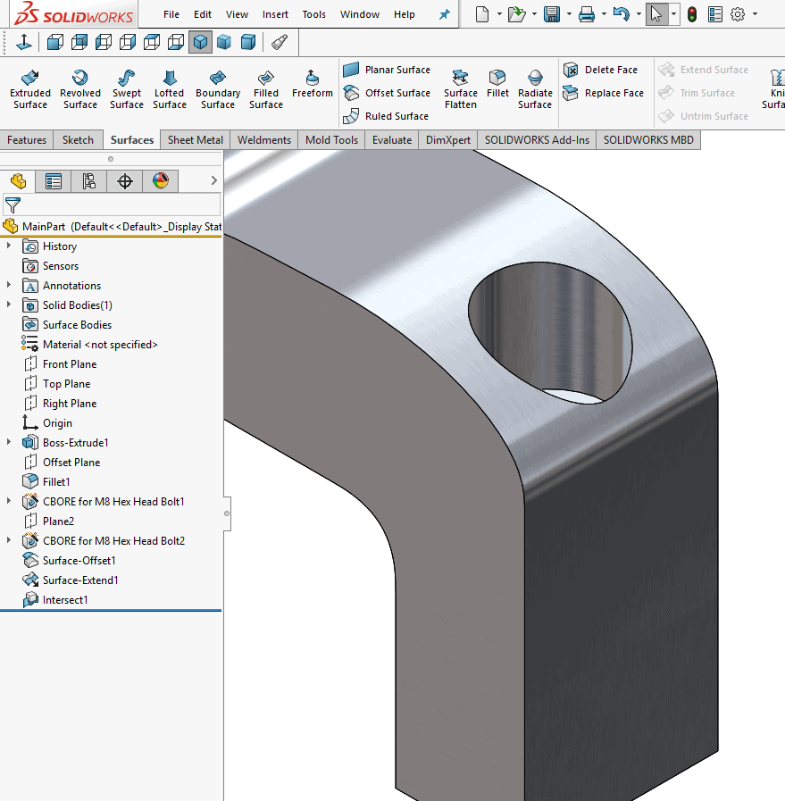
There you have it, using surfaces was not all that bad! Give it a try next time you run across an issue like this.
Ryan Field
Application Engineer, CSWE
Computer Aided Technology, Inc