SOLIDWORKS Schematic: Connectors and Components
When designing our systems in SOLIDWORKS Schematic we are sometimes faced with a component that has a connector associated with it. Another design situation is that we have components that we are designing the harness to connect them all together with. One solution would be to graphically document each portion with a symbol. That may work for some, but prove cluttered or busy to others. It also has the unwanted distinction that they have not connected the symbol to symbol. A somewhat overlooked portion of our Manufacturer Part Data answers this design step. With this in our design toolbox, we can now use the component to drive several elements of the parts needed for our design.
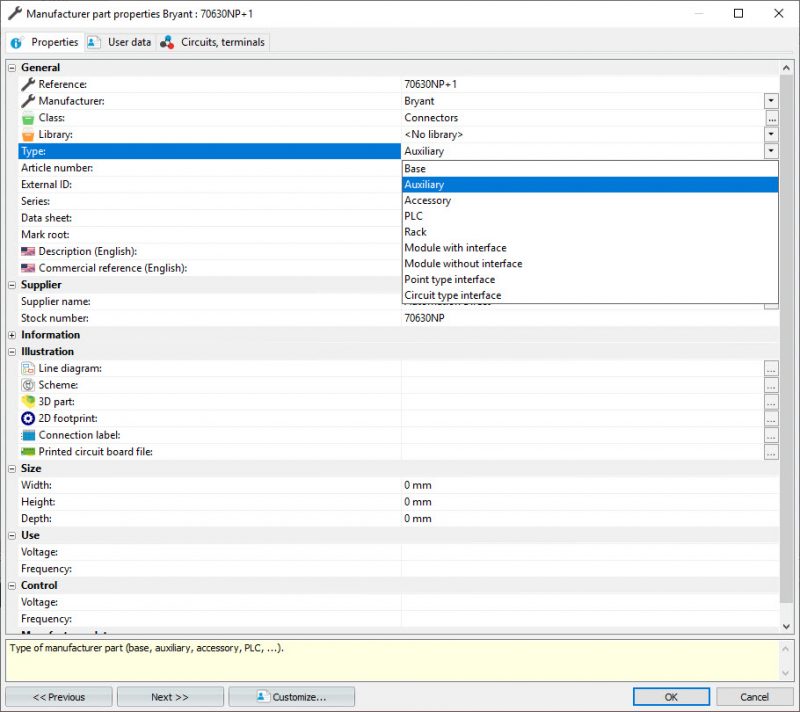
In the manufacturer part properties, Type is one attribute that is defined and there are several to choose from. We are going to focus in on the initial 3 to define a part: Base, Auxiliary, and Accessory and describe below from the help files.
- Base manufacturer part type: Components with a graphic representation in a drawing with device pin numbers displayed.
- Auxiliary manufacturer part type: Components that may have a graphic representation in a drawing which is children to a Base.
- Accessory manufacturer part type: Components that are without a graphic representation which are then children to a Base or Auxiliary.
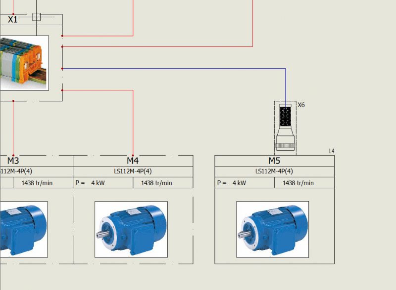
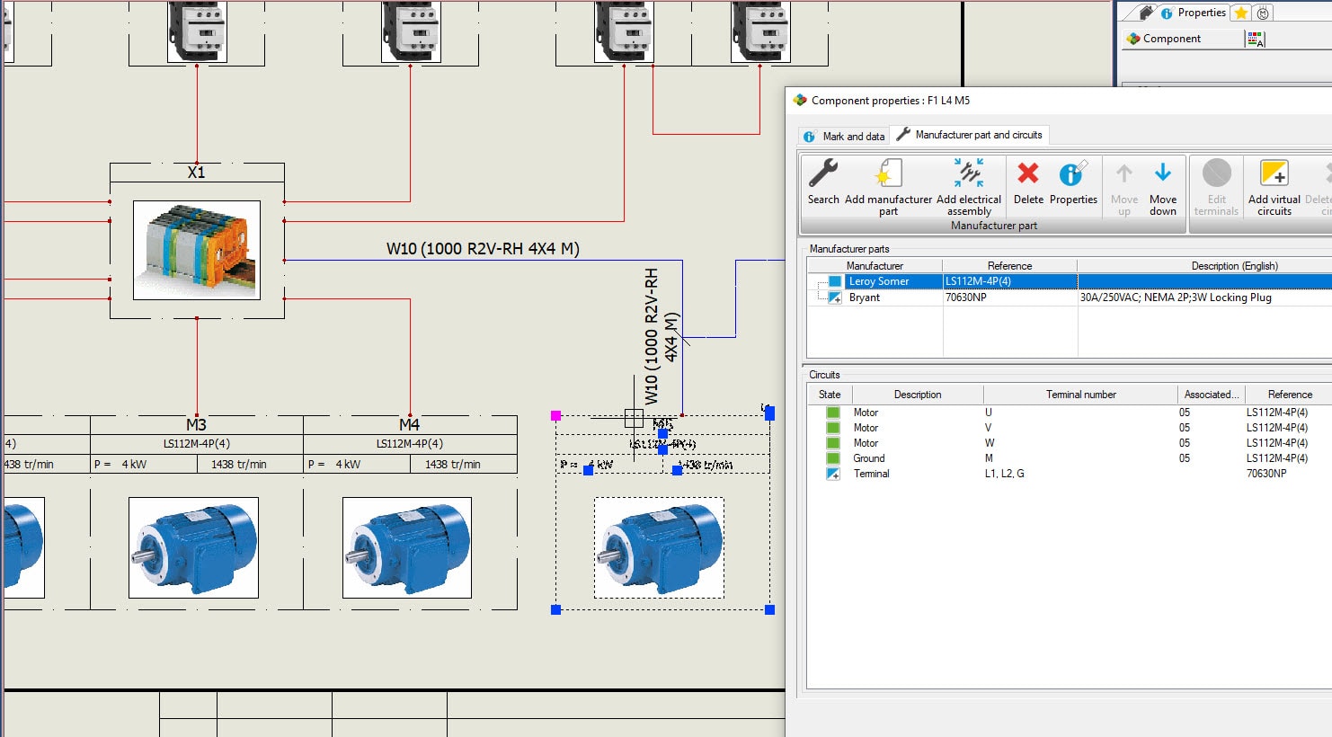
So back to our design, we are going to use a connector on our motor and have that connector in our harness assembly. In this scenario, we will add an Auxiliary part to the motor component. This Auxiliary part is our connector. We will then draw the cable to the component symbol, but use the circuits in the Auxiliary part definition. Now we have a definition to add to our harness part and our later design reports will have all the information we need.
One note to add as a shortcut would be to use Electrical Assembly part definitions, also known as Super Parts. Prior to the 2019 version, a super part would have been used. Currently, in the 2019 software release, we would define an Electrical assembly if we would like to group our component, connector, and any other parts needed under one part definition.
Corey Kubichka
CATI Electrical Product Manager
Computer Aided Technology, LLC