SOLIDWORKS – Set Up Reference Planes
Have you ever made a very complex model in SOLIDWORKS, only to find out that you need to change it? How many dimensions will you have to edit? Did you just shudder at the thought? What extremes would you go through to never have to do that again?
This kind of thought process is known as design intent. Before we start modeling, we should think about the things that could change, not just with iterations of the same design but taking the same project and copying it for another. After all, we want to design faster, and sometimes faster requires us to be smarter.
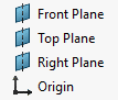
The goal of this is article is to introduce you to reference planes. It would be my number one feature I think most users’ underuse. I would also say your mating planes should be one or a combination of the Front, Top, Right Plane. They do not change, your model changes around them. Your model may change because your part faces changed, but the Front, Top, Right planes do not. So they are the most stable thing you can mate in an assembly.
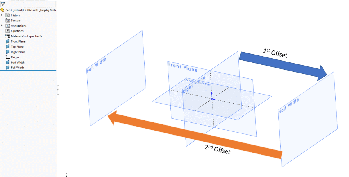
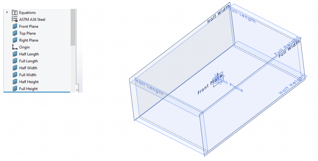
If these do not change, we should build our reference planes from them to always be constant. To illustrate this, lets build a cube, but only using planes as our dimensional boundaries. We need 6 planes and I’ll call them Half Length, Full Length, Half Width, Full Width, Half Height, Full Height. Full Plane will be our adjustment feature, half will read in Full and divide by 2 using equations. The illustration shows us how we get our planes into the model.
The next step is to double click our Half Width to display the dimension, then double click the dimension so we can edit with an equation.
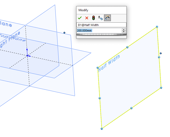
To start an Equation you just put in the equals “=”, then we double click the Full Width to display that dimension. Click to insert, then “/2”. Should look something like this: =”D1@Full Width”/2
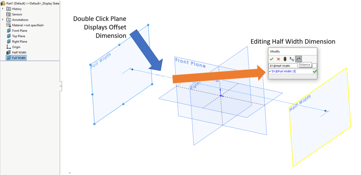
Now as you adjust Full Width to the correct size, Half Width will have the correct spacing automatically. Now to do it 2 more times for our box.
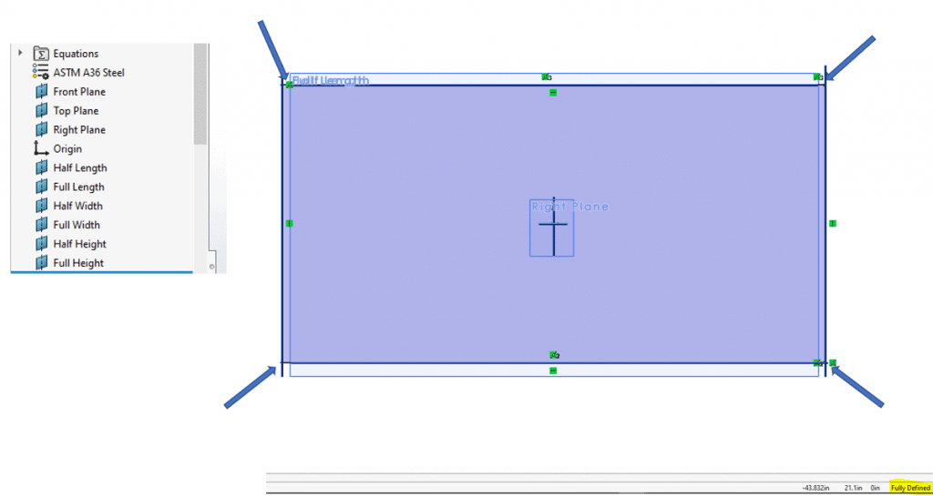
Now to put our sketch in. No dimensions, the sketch is Fully Defined, are needed as the box is going to control the size, we just need to mate the sketch points to the planes.
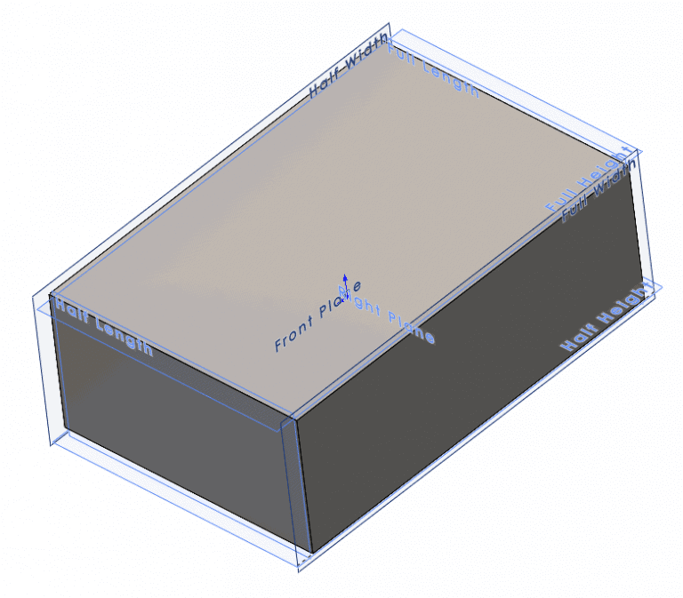
Extrude up to surface controls the extrude feature and our box is set.
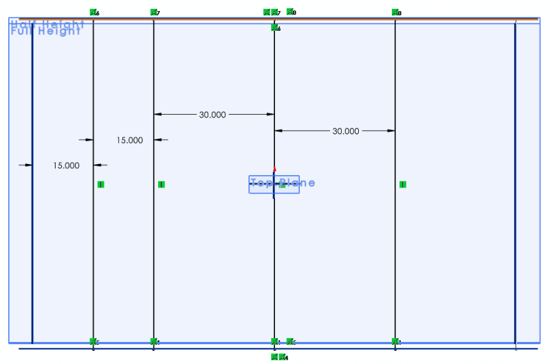
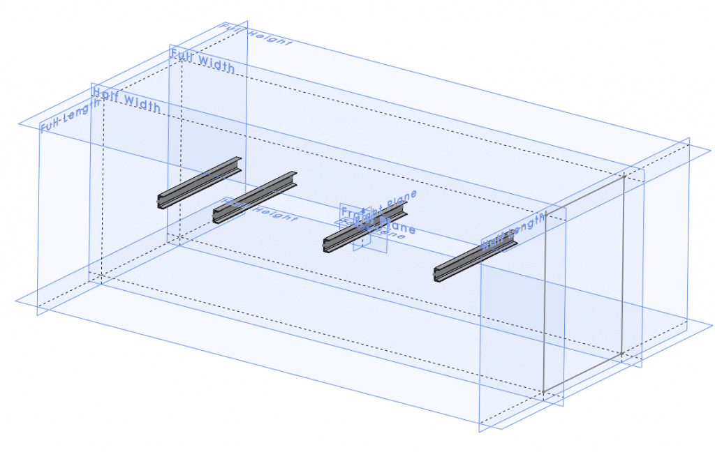
To show a more practical example we could now sketch on our Top Plane and anchor the endpoints to our new reference planes.
Make some weldments.
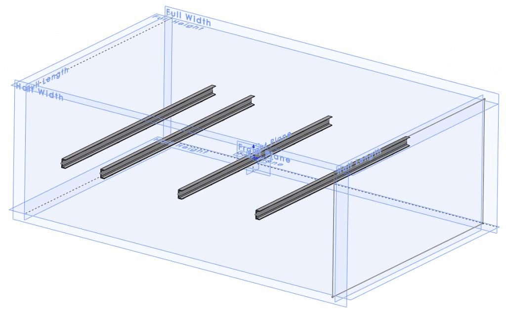
Then to change size, we simply go to the Full Plane and increase or decrease our desired value. Our model QUICKLY updates and you didn’t have to visit numerous sketches and dimensions.
Top, Front, Right Planes are also in the middle for mirroring bodies robustly and easily. Do not forget about using those planes for mating in assemblies too.
This is a simplified model of the concept, but I hope this sheds some light on how you can use reference planes to your advantage in SOLIDWORKS. Lets not forget that once we create our box, we can save that as our part template for an easy starting point.
Craig Maurer
Elite Applications Engineer
Computer Aided Technology