SOLIDWORKS Simulation: Spring Connector Differences - Face vs Point Selection
In SOLIDWORKS Simulation, anyone who uses FEA (Finite Element Analysis) and needs to simulate a spring, we know that it takes a large displacement formulation and a sizable mesh to accurately demonstrate a springs effect on an assembly. For this purpose, we have a spring connector that simulates exactly that. Although your assembly is still going through a large displacement it may or may not be going through a structural non-linearity.
Through your trials and simulations please make sure you understand what results due to the selection type. Lets start with the flat parallel face.


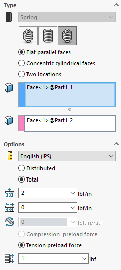
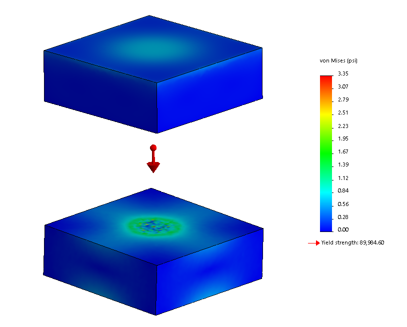
I’ve selected the two circular faces in the center of each block and only get a stress 3.35 psi under a gravitational load.
If I were to use the same numerical values and use “two locations”, the stress get concentrated at the vertex and increases two orders of magnitude to about 350 psi.
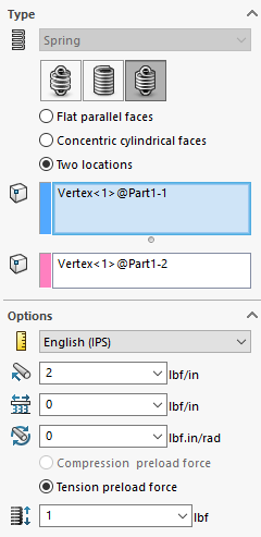
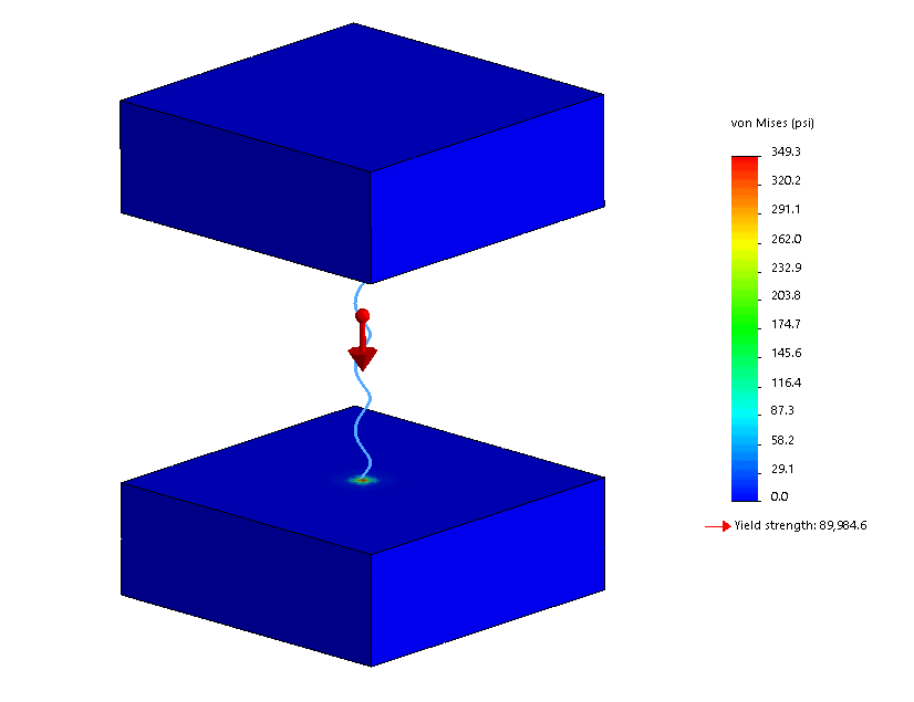
These localisations you will have to ignore if you are using the “two locations”.
Ketul Patel
Simulation Product Specialist
Computer Aided Technology, Inc