SOLIDWORKS Tools: Hole Tables
Hole Tables in SolidWorks
As engineers, we are not only responsible for the design of components, but conveying information to manufacturing professionals, such as machinists, in a clear and concise way. SolidWorks has a variety of tools that can aid in this communication, and the following article will discuss the potential of one of them, the “hole table”. The hole table is a tool that is very straight forward to use, but can save time and headaches for machine operators. This means parts can be produced and out the door in a shorter period of time, with less headaches, and less mistakes.
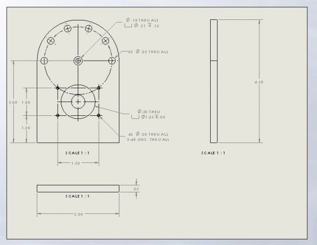
In a traditional coordinate dimensioned part such as the one below (not a complete drawing), the locations and sizes of each hole pattern can be determined. However, the machinist creating the part would have to determine coordinates of each hole pattern based on the geometry of the part. This takes time and calculations, which could result in errors that render the part useless.
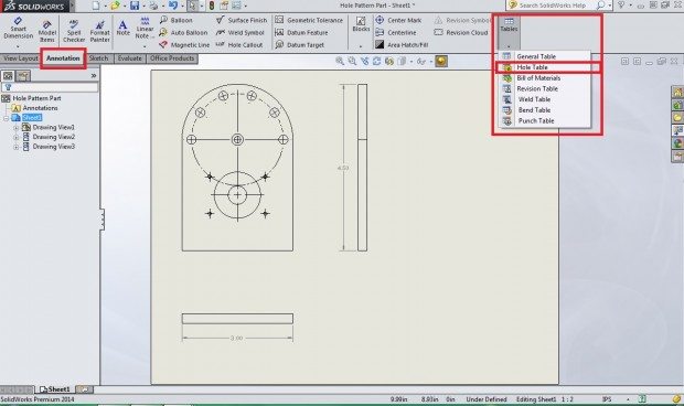
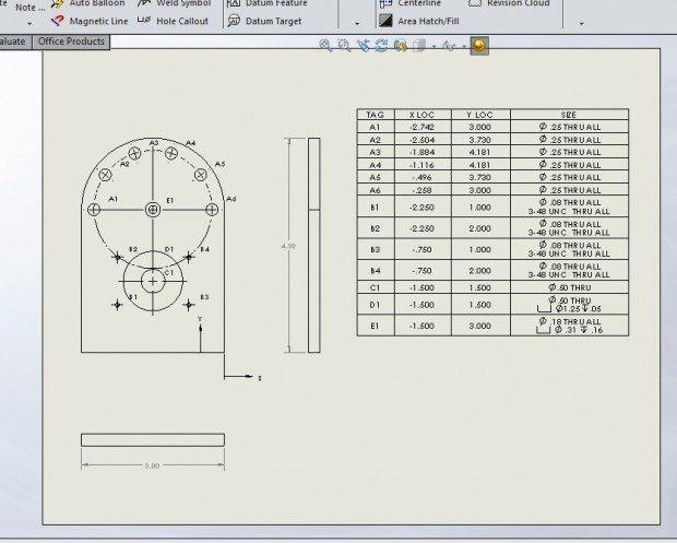
This is a perfect situation to make use of the Hole Table tool. To use this tool, create a drawing file from the desired component. Once the desired projections are inserted into the drawing, navigate to the ‘annotations’ tab, click the ‘Tables’ icon, and choose “Hole Table”.
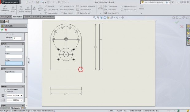
This will open the Hole Table ribbon, which is where you will select the origin of the coordinate system and the holes you wish to be identified. For this example, I chose the bottom right hand corner of the part.
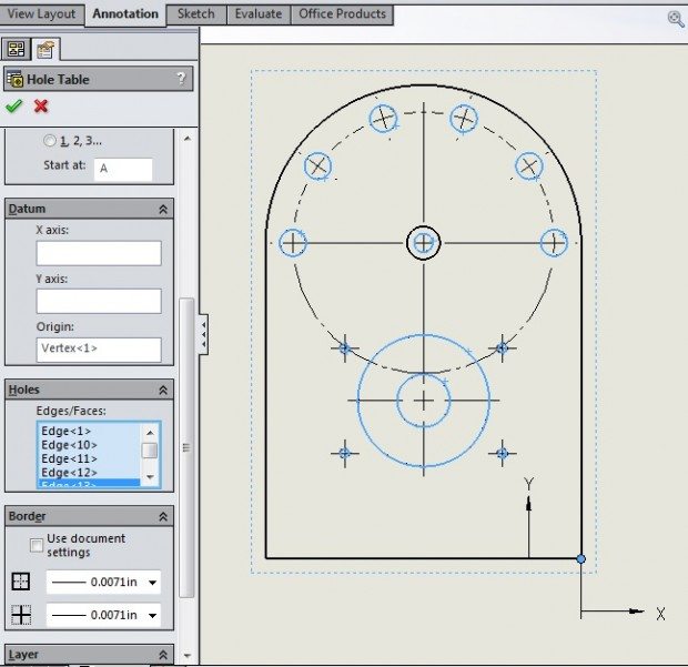
Once an origin point is selected, an x and y axis will be shown on the drawing. You can then highlight the Edge/Faces field in the ribbon and start selecting hole features. Note that features are selected by the inner most circle (a counter bore is selected by clicking just the inner diameter.)
Complete the selection by pressing the green check mark and a table that identifies each hole and its location is created. It is easy to see how clearly the information about this part is conveyed to the person reading the drawing. Now, when this part is fixtured in a mill, everything you need to know to make a CNC program and gather tooling is in one easy to read location, and any confusion that could arise from a complex technical drawing is eliminated.
Using this tool will reduce stress on your CNC operators and get higher accuracy parts out the door faster. These benefits come from only a couple minutes in SolidWorks.
Post By: Nick Weldon

 Blog
Blog 