SOLIDWORKS: Using Pattern Driven Component Patterns
Recognizing symmetry or repetition in our designs can be indication that we can save significant modeling time by capturing our design intent. In our SOLIDWORKS assemblies, we have a very powerful command called “Pattern Driven Component Pattern”. With this command, you can pattern components in your assembly based on pattern features that exist in your part files. If the feature pattern is adjusted in the part file, the patterned components will adjust to match in your assembly file. This is a great way to capture your design intent and make sure things match. This usage of Pattern Driven Component Pattern command is covered in detail in an earlier blog post.
What I wanted to show today, is another way to use this command even if the part did not actually have a pattern feature. This exception is based on part geometry created with the Hole Wizard command. It can be an excellent time saver for tasks like putting fasteners in holes.
Let’s look at a SOLIDWORKS assembly where we would like to add several fasteners to hold it together.
![]()
Let’s start by creating the screw holes in the outer blue part. For this operation, we will use the SOLIDWORKS Hole Wizard feature. To take full advantage of the Pattern Driven Component Pattern command, we want to create the holes in a single Hole Wizard feature.
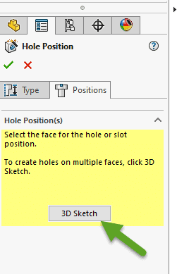
After identifying the Socket-Head Cap Screw as the type of hole geometry we need, we switch to the “Positions” tab. To place holes on multiple faces of the part, we use the “3D Sketch” button.
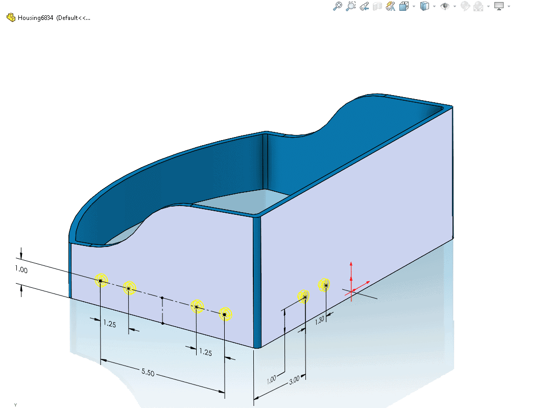
Inside this 3D Sketch, we can place sketch points to locate our holes.
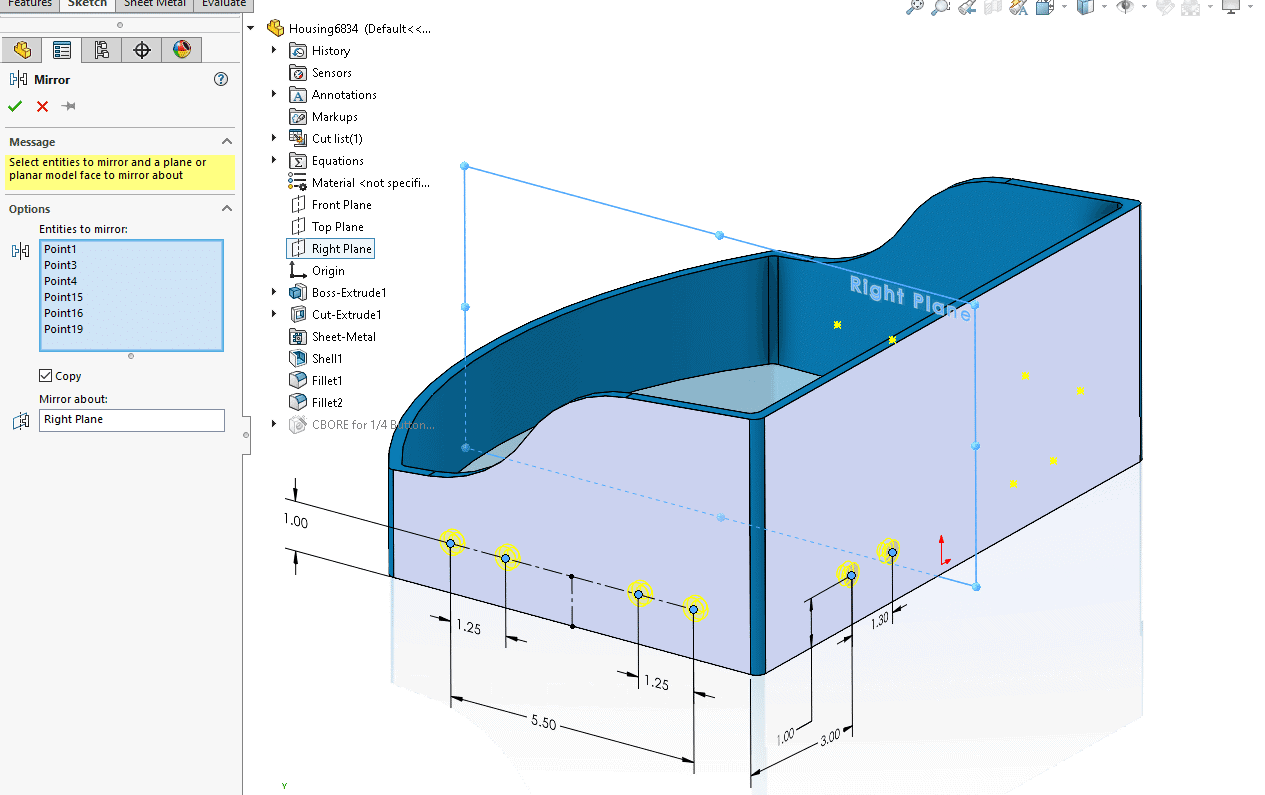
Mirroring these sketch points, inside this 3D sketch, can save us some additional time.
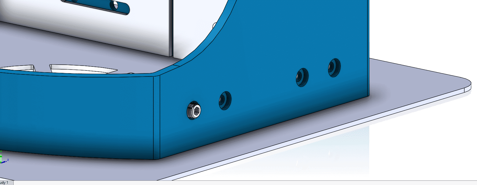
After completing the single Hole Wizard feature, we now have all twelve desired holes in the part model.
![]()
Now, let’s jump back to the assembly file. We insert the initial instance of a socket head cap screw, washer, and nut.
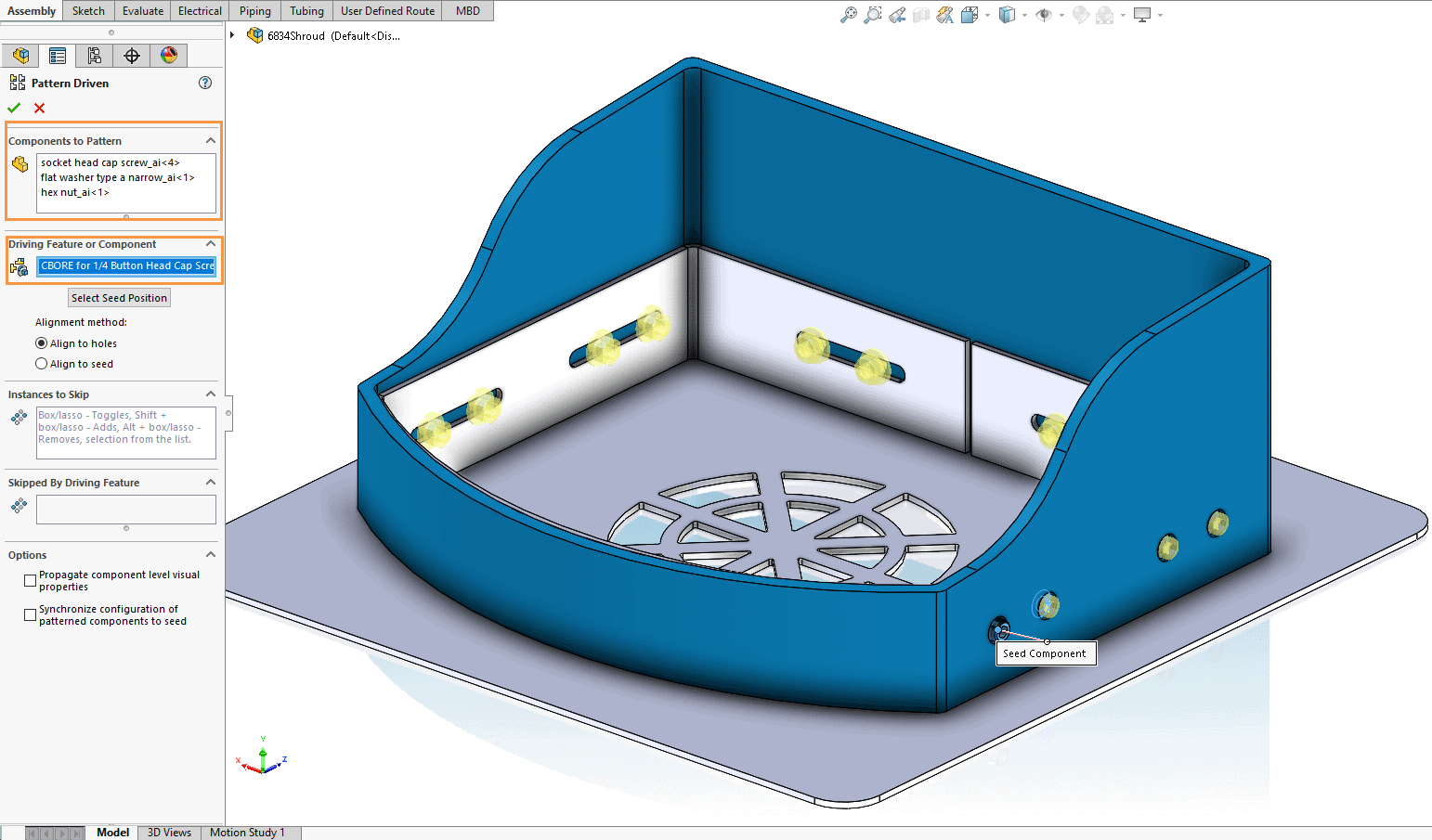
Now, we want to add several of these fastener combinations. We need one for each of these twelve bolt holes. The command we will use is Pattern Driven Component Pattern.
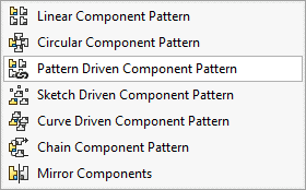
For the “Components to Pattern”, we select the nut, bolt, and washer. For the “Driving Feature” we select the Hole Wizard feature from the part file.
Mission accomplished! We have fasteners in all our bolt holes.
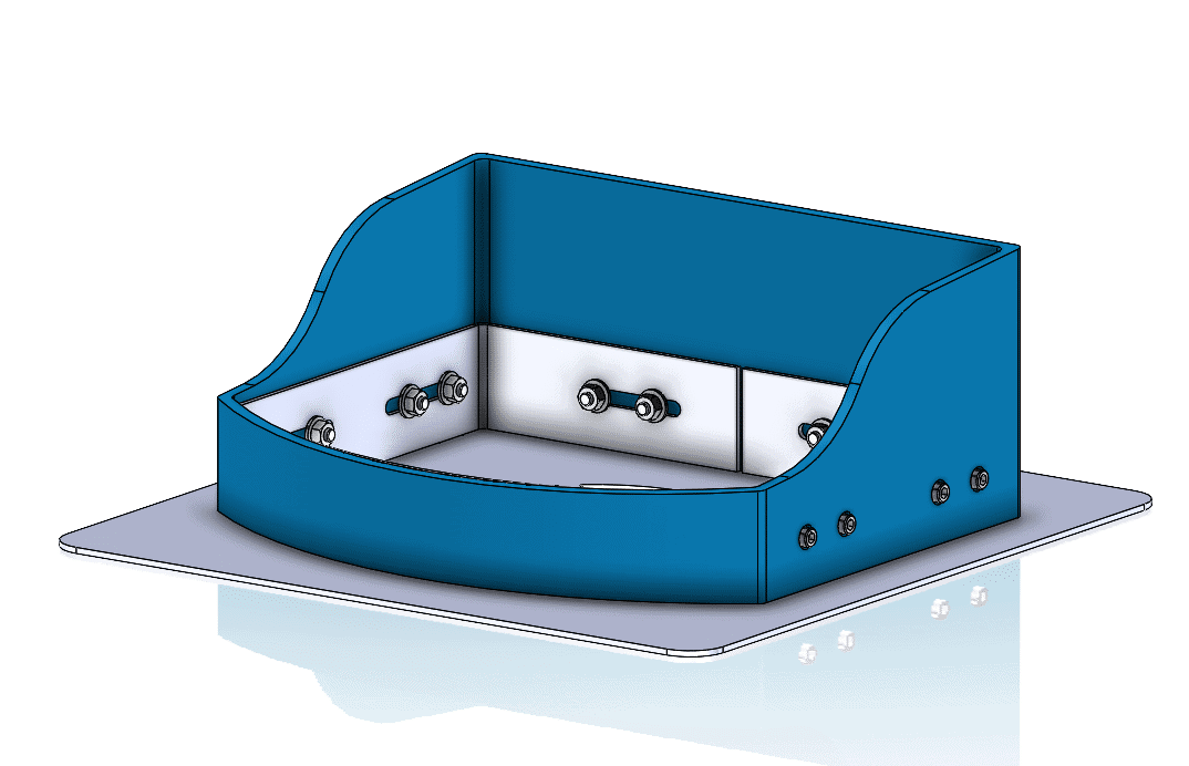
As you can see, this is a time saver and captures our design intent of fasteners in every bolt hole in the part file. If we edit the Hole Wizard hole quantity or placement, these assembly fasteners will update to match. Hopefully, this gives you additional appreciation for the very useful Pattern Driven Component Pattern tool in SOLIDWORKS.
Greg Buter
Application Engineer Manager
Computer Aided Technology