Stop Supports Spoiling Captured Inserts
Both Insight and GrabCAD Print generate support structures automatically. But what if you want to omit those structures to make room for a captured insert? Read on to learn how!
I’ve been exploring how to incorporate captured inserts into FDM 3D printed parts. Today’s topic deals with creating space within the part for that insert. To keep this article to a manageable length, I’ll focus only on removing support structures using Stratasys Insight software. Designing the pocket in 3D CAD, and manually creating support structures for special cases will be subjects for future installments.
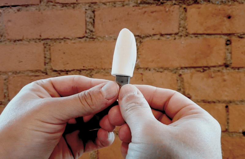
The model I’ll be working with today is a Thumb Drive, which I designed using SOLIDWORKS to accommodate an off-the-shelf USB memory stick.

Prepare The Model
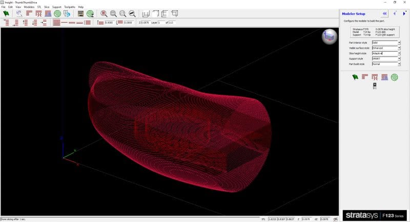
The first step is to load the STL into Insight. (Unfortunately, the tools to eliminate support structures aren’t yet available in GrabCAD Print, though you can use it to convert a parametric CAD model to STL.) It’s best to orient the model so that the flat “ceiling” of the pocket is a down-facing surface. Then slice the part. In this case, I’m using adaptive layers to improve surface finish.
If I now generate support structures, the whole pocket is filled with support material. That makes sense, to hold up that ceiling, but won’t allow space for the memory stick.
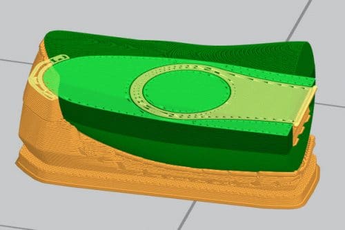
Note: Previewed in GrabCAD Print for clarity.
Remove Supports
One approach is to adjust which types of support Insight should generate. In the Support Settings window (click > Settings… > Support), notice Insight is currently configured to create “Supports and Base”. This will support overhangs in the part, and also make a base raft under the bottom layer of the part, to separate it from the build tray. For flat, simple geometries, switching to “Base Only” is a one-click solution.
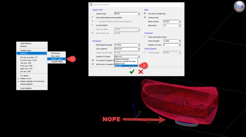
But this thumb drive is not so simple. Base Only supports won’t do the trick.
Another option is to build Partial Supports. Here I’ve entered a Z height just below the ceiling of the pocket. Now everything above this layer will be ignored the next time I generate supports.

Again, this technique would be appropriate for a simpler model, but in this case I need the fingernail to be supported. Instead, I’ll manually remove the Support curves I don’t want, using the Delete command (in the Edit Menu, or Toolbox). To ensure that I can’t accidentally remove any curves belonging to the Part or Base, I’ll set the Selection filter to only allow picking curves generated by the system for support. Then it’s just a matter of selecting those curves, and pressing OK (or delete on the keyboard). To make this easier, I’m viewing just the range of layers spanning the pocket.
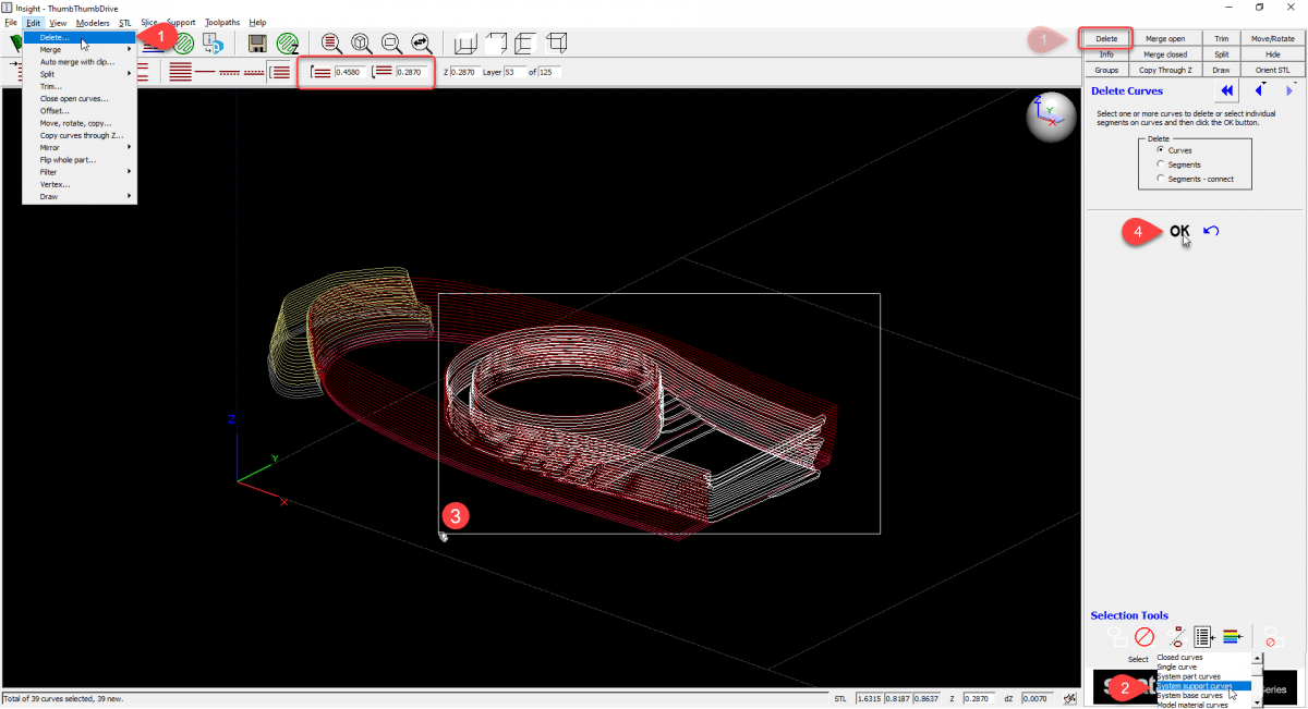
Note: If I mess something up, the Delete command does have an Undo button – or I could just regenerate support structures again.
Send the Job
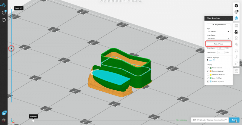
![]() Once that’s done, I’ll generate final toolpaths and verify that there is nothing in the way of inserting the memory stick. To get the very best result, I should optimize the “bridging layer” that will print on top of the memory stick and seal it in. But that’ll have to wait for another article. For now then, I’ll send this job over to GrabCAD Print, add the Pause, and send the build to the printer!
Once that’s done, I’ll generate final toolpaths and verify that there is nothing in the way of inserting the memory stick. To get the very best result, I should optimize the “bridging layer” that will print on top of the memory stick and seal it in. But that’ll have to wait for another article. For now then, I’ll send this job over to GrabCAD Print, add the Pause, and send the build to the printer!
If this article deserves a “thumbs up” (see what I did there), or if you’d like to see a specific topic covered in the future, let us know in the comments below!
Dan Erickson
Manufacturing Solutions Printed Parts Team Lead
Computer Aided Technology, Inc.